Disabling circuit in steam turbines for shutting off saturated steam

a technology of steam turbines and disabling circuits, applied in the direction of non-positive displacement fluid engines, machines/engines, engine fuctions, etc., can solve the problems of severe stress on the outer casing in terms of erosion and corrosion

Inactive Publication Date: 2013-07-04
SIEMENS AG
View PDF4 Cites 8 Cited by
  • Summary
  • Abstract
  • Description
  • Claims
  • Application Information

AI Technical Summary

Benefits of technology

[0014]In a particularly advantageous development, the first pressure space is arranged in the second flow duct, wherein the first pressure space has a pressure which is lower than the pressure in the gap space. This has the effect that the wet steam fro

Problems solved by technology

At the point where the steam flows out between the rotor and the inner casing, t

Method used


Image

  • Disabling circuit in steam turbines for shutting off saturated steam
  • Disabling circuit in steam turbines for shutting off saturated steam
  • Disabling circuit in steam turbines for shutting off saturated steam

Examples


Embodiment Construction

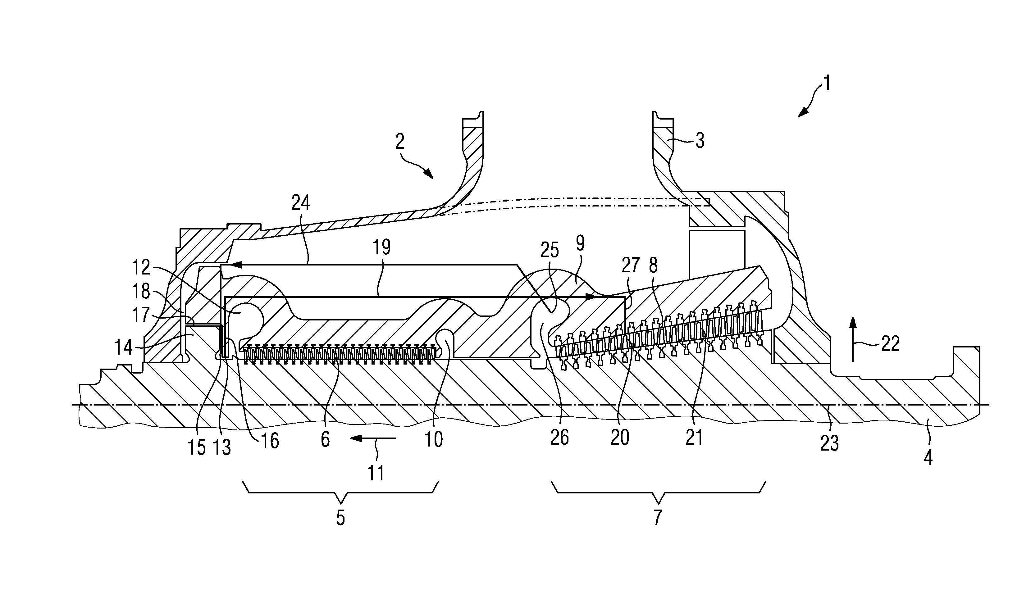
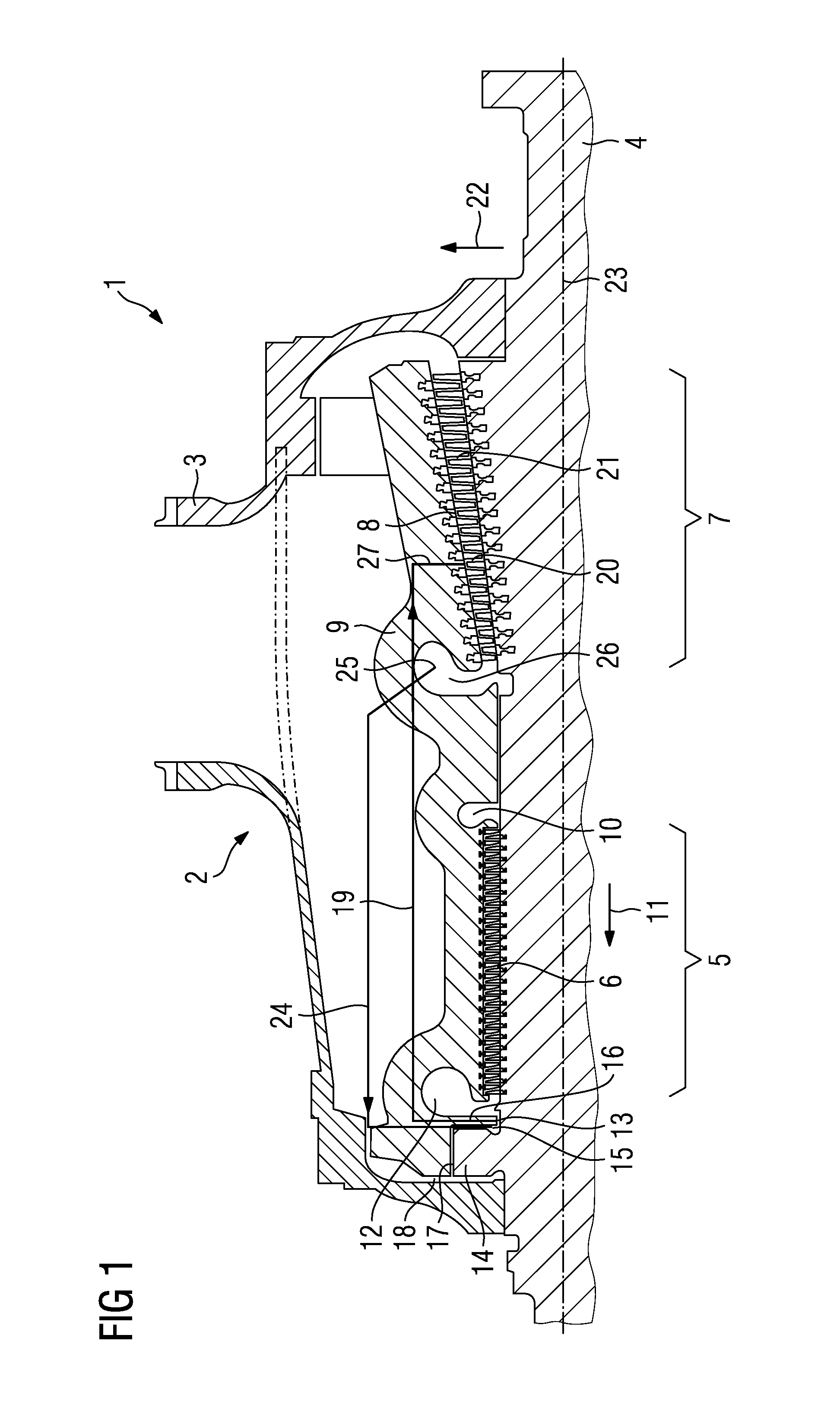
[0019]FIG. 1 shows a cross section through a steam turbine 1. The steam turbine 1 comprises a combined high-pressure and medium-pressure turbine section 2. The significant feature of the steam turbine 1 is that a common outer casing 3 is arranged around the high-pressure and medium-pressure turbine section 2. The steam turbine 1 comprises a rotor 4, on which there is a first blading region 5, which is arranged in a high-pressure flow duct 6. The rotor 5 furthermore comprises a second blading region 7, which is arranged in a medium-pressure flow duct 8. Both the high-pressure flow duct 6 and the medium-pressure flow duct 8 comprise a plurality of rotor blades (not provided with a reference sign), which are arranged on the rotor 4, and a plurality of guide blades (not provided with a reference sign), which are arranged in an inner casing 9. The terms “high-pressure turbine section” and “medium-pressure turbine section” refer to the steam parameters of the inflowing steam. Thus, the pr...


PUM


Abstract

A cooling option for a steam turbine is provided, wherein the steam turbine includes a high-pressure zone and a medium-pressure zone, wherein the saturated steam streaming out of the high-pressure zone is discharged via a saturated steam conduit to a first pressure chamber in a second flow channel of the medium-pressure zone and thus the possibility of the saturated steam causing damage by corrosion and erosion in the high-pressure zone is prevented.

Description

CROSS REFERENCE TO RELATED APPLICATIONS[0001]This application is the US National Stage of International Application No. PCT / EP2011 / 065909, filed Sep. 14, 2011 and claims the benefit thereof. The International Application claims the benefits of European Patent office application No. 10177090.7 EP filed Sep. 16, 2010. All of the applications are incorporated by reference herein in their entirety.FIELD OF INVENTION[0002]The invention relates to a steam turbine comprising a rotatably mounted rotor, an inner casing and a high-pressure flow duct arranged between the rotor and the inner casing, wherein the rotor has a dummy piston, wherein the steam turbine has a dummy piston line, wherein the dummy piston line opens into a dummy piston prechamber.BACKGROUND OF INVENTION[0003]For thermodynamic reasons, steam turbines are used at relatively high temperatures. Recent development in modern turbomachine construction has tended toward planning for temperatures of over 700° C., and even over 720...

Claims


Application Information

Patent Timeline
IPC IPC(8): F01D25/24
CPCF01D3/04F05D2220/31F01D25/24F05D2260/95F05D2260/608F01D25/007F01D3/02
Inventor ALMSTEDT, HENNINGDUMSTORFF, PETERKUHN, MARTINMULLER, THOMASPOTTER, RUDOLFTHAMM, NORBERTZANDER, UWE
Owner SIEMENS AG
Why Eureka
Try Eureka