Separation membrane, separation membrane element, and method for producing separation membrane

a separation membrane and element technology, applied in the direction of membranes, filtration separation, separation processes, etc., can solve the problems of insufficient flow resistance-reducing effect on both feed side and permeate side, and insufficient flow resistance-reducing effect, etc., to achieve excellent chemical resistance to acidity, high efficiency, and stable flow

Inactive Publication Date: 2013-07-11
TORAY IND INC
View PDF0 Cites 10 Cited by
  • Summary
  • Abstract
  • Description
  • Claims
  • Application Information

AI Technical Summary

Benefits of technology

[0018]A method is provided for producing a separation membrane, the method including: arranging a forming component on one surface of a work-in-process separation membrane; and while the forming component is thus kept arranged thereon, pressing the work-in-process separation membrane from the other surface thereof by a liquid or vapor applied thereto, having a temperature of from 50° C. to 100° C., thereby forming height differences on the surface of the work-in-process separation membrane.
[0019]According to the invention, owing to the height differences formed on at least one surface of the separation membrane, highly-efficient and stable flows can be secured both on the feed side and on the permeate side with no use of a feed-side passage member such as a net and a permeate-side passage member such as a tricot. Further, during forming, surface defects hardly form on the surface of the membrane and the membrane is excellent in chemical resistance to acid, alkali and the like, and as a result, there can be obtained high-performance and highly-efficient separation membrane and separation membrane element excellent in the performance of removing separated components and in the permeability performance.

Problems solved by technology

The above-mentioned separation membrane elements could not be said to be sufficient in point of the performance increase, especially in point of the stability performance in long-term use.
For example, in the method of using the concavoconvex-embossed sheets as the permeate-side passage member described in Patent Document 1, merely the flow resistance on the permeate side can be reduced, but the flow resistance-reducing effect could not be said to be sufficient since there still exists sheet surface resistance.
Additionally, since the shapes of the permeate-side passages are also limited, the flow resistance-reducing effect on both the feed side and the permeate side could not be said to be sufficient.

Method used


Image

  • Separation membrane, separation membrane element, and method for producing separation membrane
  • Separation membrane, separation membrane element, and method for producing separation membrane
  • Separation membrane, separation membrane element, and method for producing separation membrane

Examples


first embodiment

1. First Embodiment

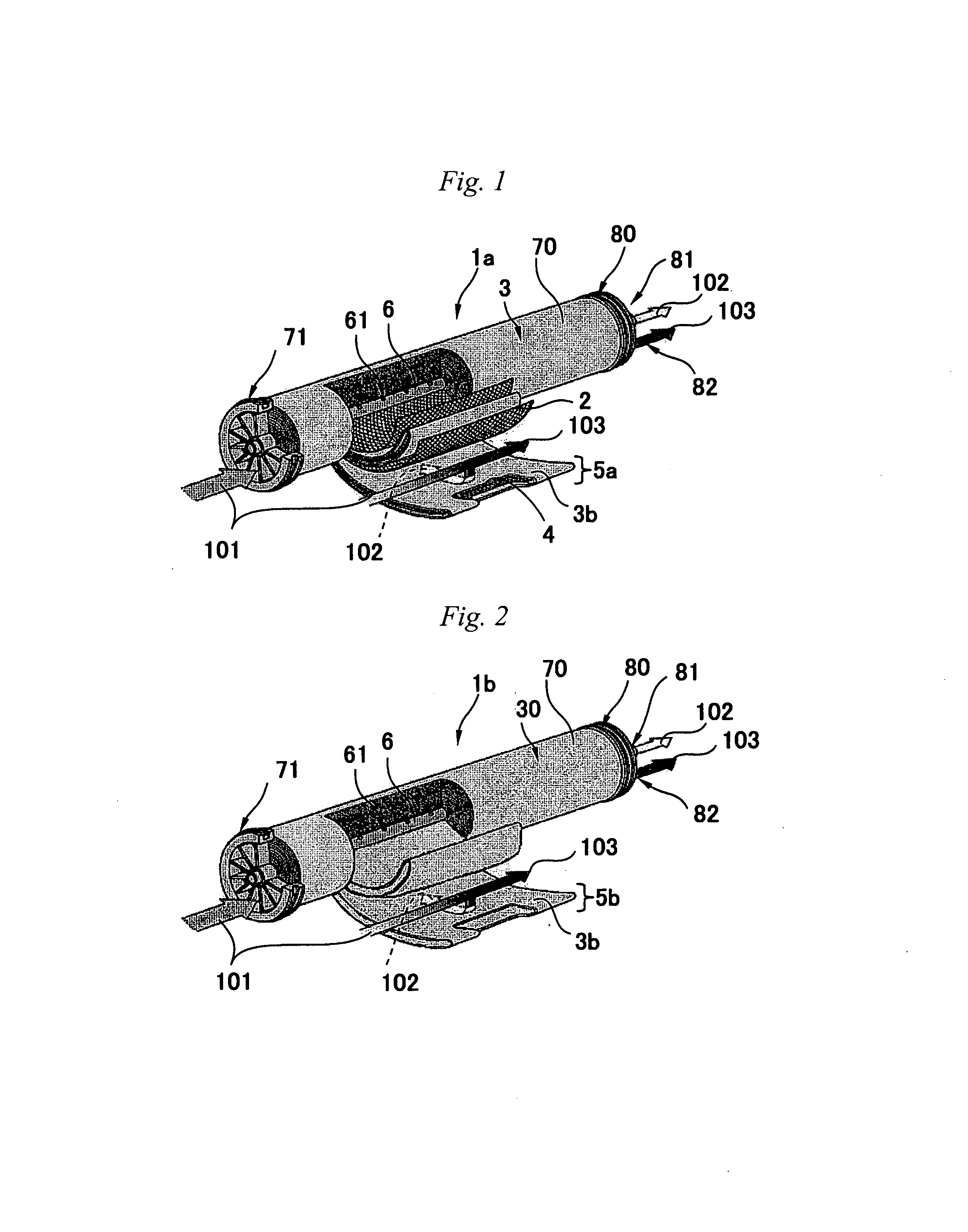
[0178]As shown in FIG. 1, the spiral-type separation membrane element 1a separates the raw fluid 101 into a permeated fluid 102 and a concentrated fluid 103. The separation membrane element 1a comprises a perforated water-collecting tube 6, a separation membrane 3b, a first end plate 71, a second end plate 80 and a filament winding 70.

[0179]The perforated water-collecting tube 6 is a tube that is hollow inside it, and its surface has a large number of pores each communicating with the inside. As the material of the tube, usable are various materials including hard plastics such as PVC, ABS, etc., or metals such as stainless, etc. The number of the perforated water-collecting tube to be arranged in one separation membrane element is basically 1 (one). As described below, the permeated fluid 102 that has passed through the separation membrane is collected by the perforated water-collecting tube 6.

[0180]The separation membrane 3b is arranged to surround the perforate...

second embodiment

2. Second Embodiment

[0190]In the following, the members that have been already described with reference to FIG. 1 are given the same reference numerals or signs and their description is omitted here.

[0191]As shown in FIG. 2, the separation membrane element 1b of this embodiment has the same configuration as that of the separation membrane element 1a of the first embodiment except that this has neither a net nor a tricot as the passage members. Specifically, the wound body 30 of the separation membrane element 1b is provided with neither the net 2 nor the tricot 4 shown in FIG. 1, but has only the surrounding envelope-like membrane 5b.

third embodiment

3. Third Embodiment

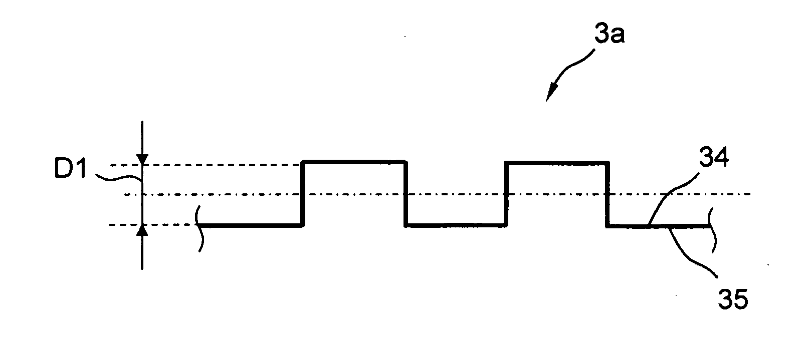
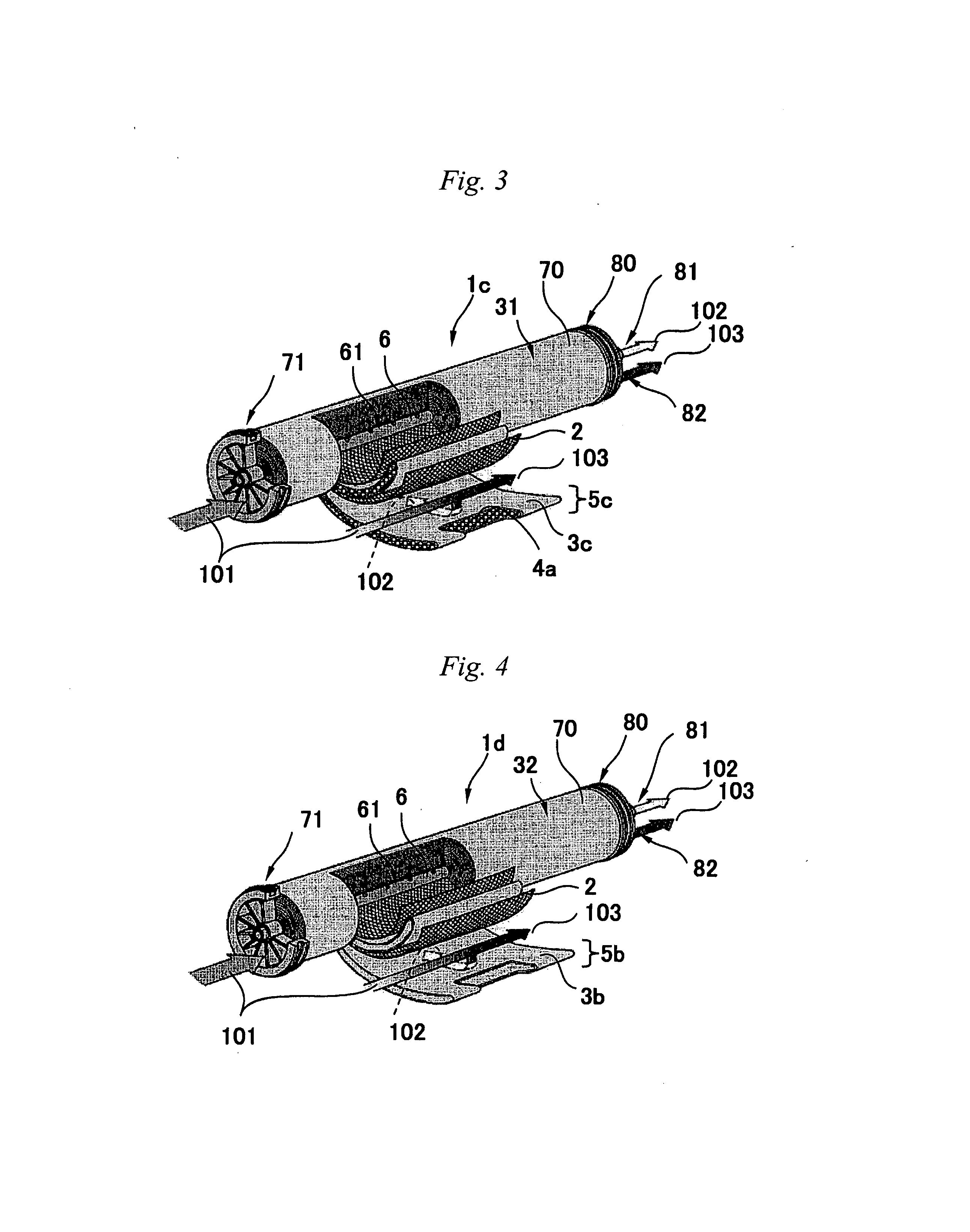
[0192]For producing the intended separation membrane element, the permeated passage member is changed to a forming component to produce the element; and the separation membrane element is given running water under pressure to thereby prepare the membrane have concavoconvex parts. A specific configuration is described with reference to FIG. 3.

[0193]As shown in FIG. 3, the separation membrane element 1c of this embodiment has the same configuration as that of the conventional spiral-type separation element 1a shown in FIG. 1, except that it has a forming component 4a in place of the tricot 4.

[0194]Specifically, in the wound body 31 of the separation membrane element 1c, concavoconvex parts need not to be formed in the separation membrane 3c before fluid application. The forming component 4a is arranged on the permeate-side surface of the separation membrane 3c in the wound body 31.

[0195]The raw fluid 101 is applied under pressure to the separation membrane element 1...


PUM

PropertyMeasurementUnit
heightaaaaaaaaaa
temperatureaaaaaaaaaa
depthaaaaaaaaaa

Abstract

The present invention provides a separation membrane having a plurality of concavoconvex parts which have a height difference of from 100 μm to 2000 μm and are formed on at least one surface of the separation membrane, in which an average value d1 of a minimum thickness and an average value d2 of a maximum thickness in the concavoconvex parts satisfy the following relational expression
0.8≦d1/d2≦1.0.  [1]

Description

CROSS REFERENCE TO RELATED APPLICATIONS[0001]This application is the U.S. National Phase application of PCT International Application No. PCT / JP2011 / 070240, filed Sep. 6, 2011, and claims priority to Japanese Patent Application No. 2010-199558, filed Sep. 7, 2010, the disclosure of both are incorporated herein by reference in their entireties for all purposes.FIELD OF THE INVENTION[0002]The present invention relates to a separation membrane and a separation membrane element to be used for separating components contained in fluid such as liquid or vapor, and relates to a method for producing the separation membrane.BACKGROUND OF THE INVENTION[0003]Various methods are known for separating components contained in fluid such as liquid or vapor. For example, a case of a technique for removing ionic substances contained in seawater, brine water or the like is described, for which, recently, use of a separation method with a separation membrane element has become expanding as a process for...

Claims


Application Information

Patent Timeline
Patent Type & Authority Applications(United States)
IPC IPC(8): B01D69/02
CPCB01D63/10B01D67/0006B01D67/0083B01D67/0086B01D69/02B01D69/06B01D2325/30B01D69/125B01D71/16B01D71/56B01D2323/40B01D2325/06B01D69/10B01D69/12B01D69/00
Inventor TAKAGI, KENTAROKIMURA, MASAHIROHIROZAWA, HIROHO
Owner TORAY IND INC
Why Eureka
Try Eureka