System, Apparatus, and Method for Reducing Inrush Current in a Three-Phase Transformer

Active Publication Date: 2013-07-11
SCHWEITZER ENGINEERING LABORATORIES
View PDF0 Cites 13 Cited by
  • Summary
  • Abstract
  • Description
  • Claims
  • Application Information

AI Technical Summary

Benefits of technology

[0010]Accordingly, it is a general object of the present disclosure to reduce transformer inrush current in a three-phase power system.
[0011]It is a more specific object of the present disclosure to provide a system, apparatus and method for automatically establishing residual flux levels in the transformer's core segments such that the transformer can be energized with reduced inrush current in the windings.
[0012]It is a still more specific object of the present disclosur

Problems solved by technology

Such high transformer inrush currents have a number of potentially adverse effects.
For one, a high inrush current can significantly heat transformer windings and cause deterioration of insulation in the transformer.
In addition, high inrush currents can place large mechanical stresses on the transformer windings sufficient to displace the windings on the transformer core, which, in the worst case, can break electrical connections within the transformer.
Moreover, insulation compression from displacement of the transformer windings can result in turn-to-turn faults within the transformer, which, if left undetected, can eventually destroy the transformer.
Large inrush currents can also disrupt a power system by inappropriately

Method used


Image

  • System, Apparatus, and Method for Reducing Inrush Current in a Three-Phase Transformer
  • System, Apparatus, and Method for Reducing Inrush Current in a Three-Phase Transformer
  • System, Apparatus, and Method for Reducing Inrush Current in a Three-Phase Transformer

Examples


Example

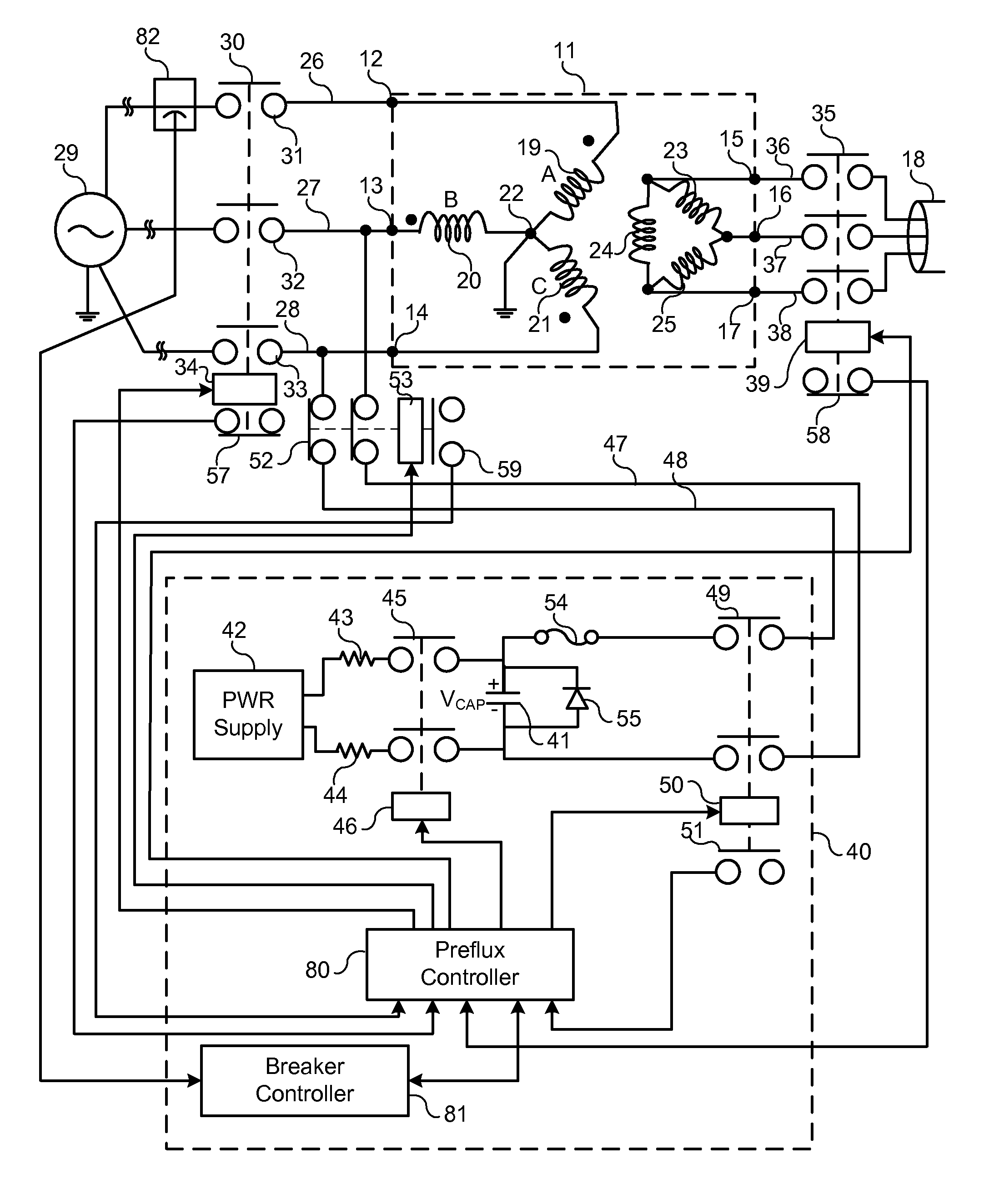
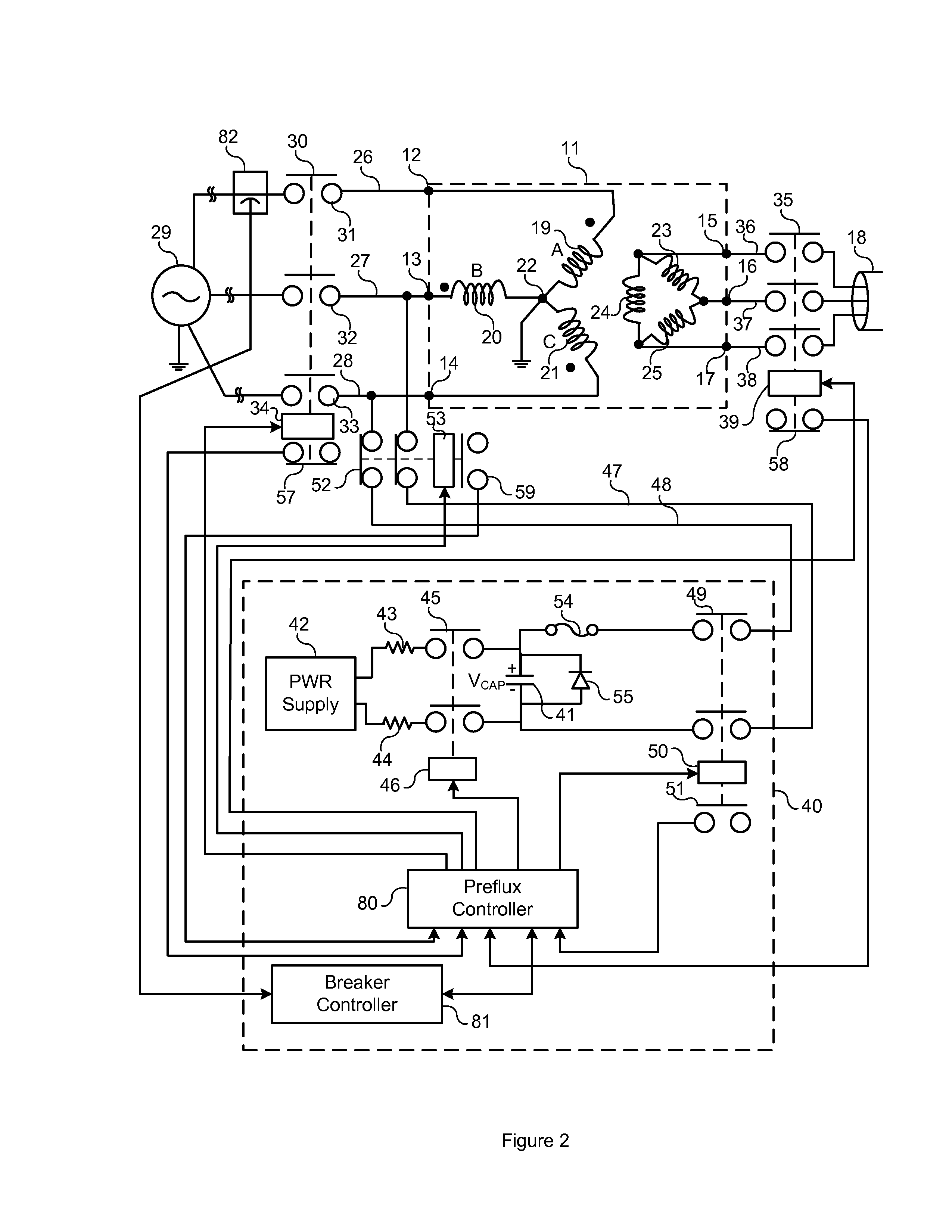
[0025]One method proposed by the present inventor for reducing inrush current in a single-phase transformer involves establishing a residual flux in the transformer core by means of a pre-fluxing circuit attached to one of the transformer's windings. The residual flux established in the transformer core approaches the prospective flux (the flux in the transformer core under steady state conditions) which will be produced when the winding is energized at a specific system voltage angle. As a consequence, inrush current to the pre-fluxed winding can be significantly reduced upon energization of the winding. The pre-fluxing device establishes the appropriate residual flux in the transformer core by supplying an appropriate amount of volt-seconds, also known as flux linkages, to the transformer core.

[0026]The system of the present disclosure reduces inrush current in a three-phase transformer by simultaneously establishing residual flux levels in each of the three core segments associat...


PUM


Abstract

A system for reducing inrush current in a three phase utility transformer upon energization of the transformer by an applied three phase voltage utilizes a pre-flux circuit for establishing residual flux levels in the core segments of the primary windings of the transformer which are near the prospective flux levels established in the core segments by the applied voltage. The pre-flux circuit includes a pre-fluxing capacitor which, after being charged to a predetermined voltage level, is discharged serially through two of the primary windings to establish the predetermined flux levels in the core segments of the two windings, and a reduced flux level in the core segment of the remaining primary winding. The transformer is energized at the instant of positively-referenced peak phase voltage to the third primary winding such that prospective and residual flux approach a near-equal level in all three core segments and inrush current is reduced. The method may be applied to the secondary or tertiary windings instead of the primary windings. Additionally, an alternative method allows application of the pre-fluxing circuit to a delta-connected set of transformer windings.

Description

CROSS-REFERENCE TO RELATED APPLICATIONS[0001]None.BACKGROUND OF THE INVENTION[0002]The present invention relates generally to transformer inrush current reduction, and more specifically, to a system, apparatus, and method for reducing inrush current when energizing a three-phase transformer.[0003]When energizing a three-phase transformer in an electric power delivery system (such as an electric power generation, transmission, or distribution system, or the like), inrush currents may occur which can be as large as ten times the transformer's nominal current and can last for up to around half of a second. The actual magnitude of these inrush currents depends on the impedance of the source supplying the transformer, the residual magnetic flux existing in the transformer, and the angle of the applied voltage at the time of energization.[0004]Such high transformer inrush currents have a number of potentially adverse effects. For one, a high inrush current can significantly heat transform...

Claims


Application Information

Patent Timeline
IPC IPC(8): H01H47/00
CPCH02H7/04H02H9/002
Inventor TAYLOR, DOUGLAS I.
Owner SCHWEITZER ENGINEERING LABORATORIES
Why Eureka
Try Eureka