Valve, fluid control device

a fluid control device and valve body technology, applied in the direction of diaphragm valves, instruments, angiography, etc., can solve the problems of increased power consumption, increased manufacturing costs, and increased sphygmomanometers, and achieve small and low-profile fluid control, low manufacturing costs, and small power consumption

Active Publication Date: 2013-07-11
MURATA MFG CO LTD +1
View PDF19 Cites 54 Cited by
  • Summary
  • Abstract
  • Description
  • Claims
  • Application Information

AI Technical Summary

Benefits of technology

[0044]With this configuration, the fluid control device is, for example, an electronic sphygmomanometer. With this configuration, by using any one of the valves according to the preferred embodiments described above, a similar effect is achieved even for a fluid control device equipped with the valve. Furthermore, according to this configuration, an electromagnetic valve which is hard to be miniaturized and a driver circuit that drives the electromagnetic valve are not provided, so that a small and low profile fluid control device can be provided with low manufacturing costs and small power consumption.
[0045]It is to be noted that, with this configuration, the pump may include, for example, an actuator of which the peripheral portion is not substantially fixed and which bends and vibrates from the central portion to the peripheral portion; and

Problems solved by technology

Therefore, the manufacturing costs may become higher, and the main body of the electronic sphygmomanometer may become larger, and the power consumption may increase.
However, the volume of the air that can be stored in the cuff is extremely large as compared with the volume of the pump chamber of

Method used


Image

  • Valve, fluid control device
  • Valve, fluid control device
  • Valve, fluid control device

Examples


Embodiment Construction

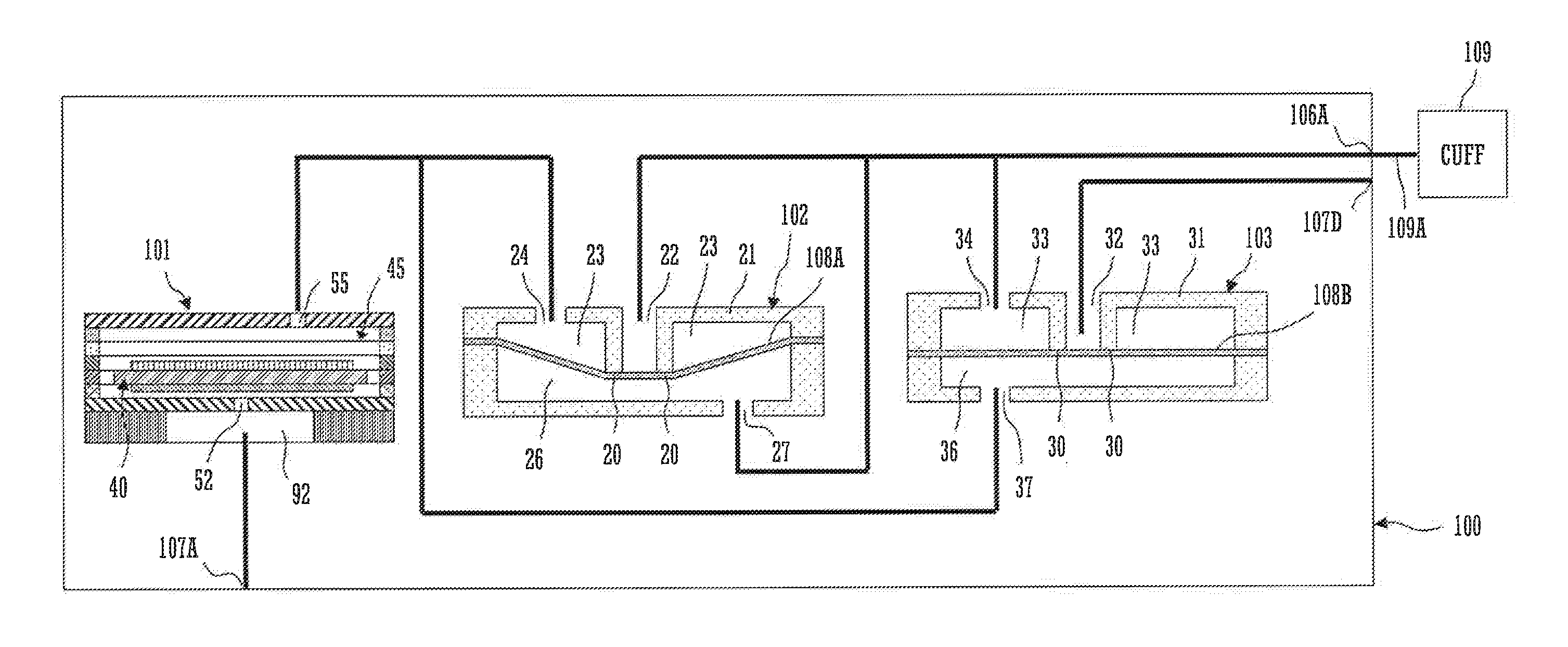
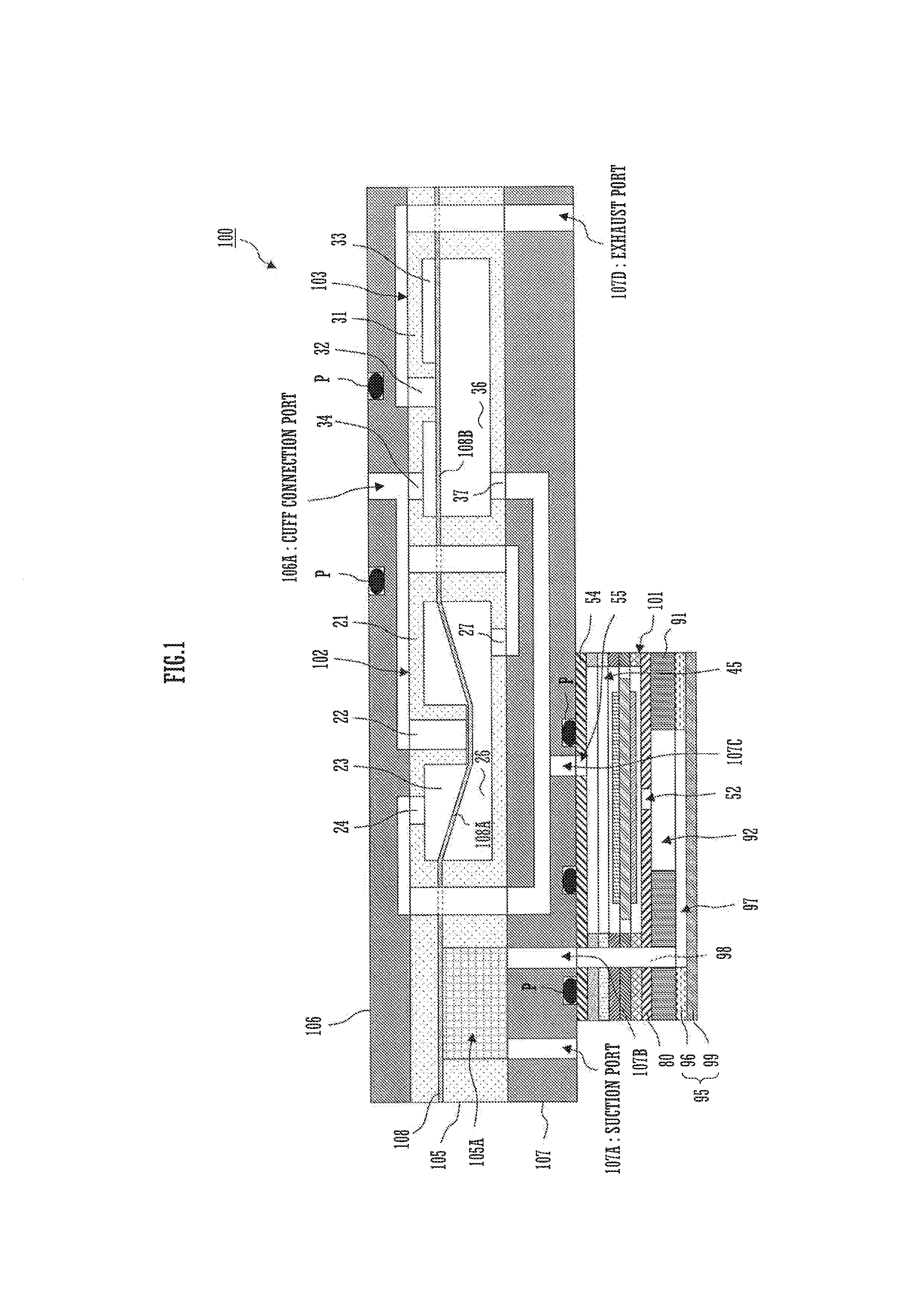
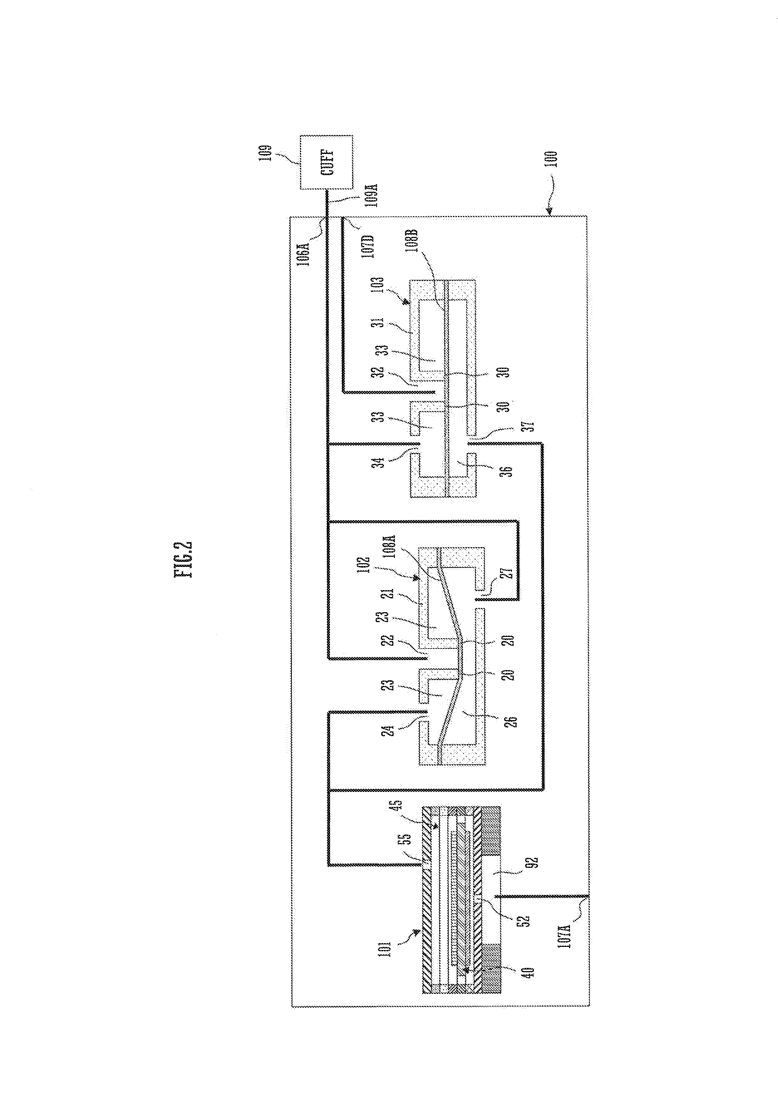
[0088]Hereinafter, a fluid control device 100 according to a first preferred embodiment of the present invention will be described. FIG. 1 is a cross sectional view of the main portion of the fluid control device 100 according to the first preferred embodiment of the present invention. FIG. 2 is an explanatory view showing the connection relationship among a piezoelectric pump 101, a check valve 102, an exhaust valve 103, and a cuff 109 that are shown in FIG. 1. The fluid control device 100 has a structure in which the piezoelectric pump 101, a base plate 107, a valve housing 105 that defines, together with a diaphragm 108, a dustproof filter 105A, the check valve 102, and the exhaust valve 103, and a lid element 106 are laminated in this order. In other words, the piezoelectric pump 101, the check valve 102, and the exhaust valve 103 are preferably formed integrally. With this structure, the fluid control device 100 is equipped with the piezoelectric pump 101, the check valve 102, ...


PUM


Abstract

In a fluid control device, a check valve includes a first valve housing and a first diaphragm. The first diaphragm defines a first valve chamber and a second valve chamber. An exhaust valve includes a second valve housing and a second diaphragm. The second diaphragm defines a third valve chamber and a fourth valve chamber. The check valve is opened and closed by a difference in pressure between the first valve chamber and the second valve chamber. The exhaust valve is opened and closed by a difference in pressure between the third valve chamber and the fourth valve chamber.

Description

BACKGROUND OF THE INVENTION[0001]1. Field of the Invention[0002]The present invention relates to a valve suitable for a fluid control device that charges compressed air into an air reservoir and exhausts the air from the air reservoir, and relates to the fluid control device.[0003]2. Description of the Related Art[0004]A conventional electronic sphygmomanometer is disclosed in Japanese Examined Utility Model Application Publication No. 61-32645. This electronic sphygmomanometer is connected to a cuff through an armband rubber tube. This electronic sphygmomanometer stores in a body case: a pressure pump that sends air out to the cuff; a pressure sensor that converts a cuff pressure into an electronic signal; an electromagnetic valve that is opened according to the electric signal, and rapidly reduces the cuff pressure; a constant speed reducing pressure valve that reduces the cuff pressure at a constant speed; and a driver circuit that generates an electric signal and transmits the e...

Claims


Application Information

Patent Timeline
IPC IPC(8): A61B5/0235
CPCF16K7/17A61B5/0235F04B43/046F16K15/144Y10T137/7836Y10T137/86019Y10T137/87185F04B49/225F16K15/145F16K24/04G05D7/0113
Inventor KODAMA, YUKIHARUHIRATA, ATSUHIKOSANO, YOSHIHIKOOGURA, TOSHIHIKODOI, YOSHIKI
Owner MURATA MFG CO LTD
Why Eureka
Try Eureka