Connecting mechanism having two contacts with contact surfaces inclined in a direction perpendicular to their mating direction

a technology of connecting mechanism and contact surface, which is applied in the manufacture of contact members, coupling device connections, fixed connections, etc., can solve the problems of small and low profile connecting mechanism, shorten the life of the connecting mechanism, and reduce the amount of electricity to be fed across the contacts. , to achieve the effect of greater freedom

Active Publication Date: 2017-03-07
ORMON CORP
View PDF18 Cites 0 Cited by
  • Summary
  • Abstract
  • Description
  • Claims
  • Application Information

AI Technical Summary

Benefits of technology

[0012]According to one aspect of the invention of the connecting mechanism, this ensures an increased contact area between the first contact and the second contact, which is larger than that can be formed by contact surfaces parallel to the orthogonal planes. This reduces a contact resistance, which in turn reduces heat to be generated at the contact surfaces and increases current capacity. This also reduces a contact force and a resultant frictional damage to be applied on the contact surfaces at the insertion of the first contact into the second contact, which in turn reduces frictional damages, which ensures an extended life span of the connecting mechanism. It may not be restricted that the first surface is parallel to the second surface.
[0032]According to this aspect of the invention, this ensures an increased contact area between the first contact and the second contact, which is larger than that can be formed by contact surfaces parallel to the orthogonal planes. This reduces a contact resistance, which in turn reduces heat to be generated at the contact surfaces and increases current capacity. This also reduces a contact force and a resultant frictional damage to be applied on the contact surfaces at the insertion of the first contact into the second contact, which in turn reduces frictional damages, which ensures an extended life span of the connecting mechanism. Furthermore, a small and low profile connecting mechanism is provided in a few manufacturing process.

Problems solved by technology

A recent trend of miniaturization of the connector results in a small and low profile connecting mechanism.
This necessarily decreases a contact area of the contacts and thereby increases a contact resistance and an amount of heat generated at the contact portions, which eventually reduces an amount of electricity to be fed across the contacts.
Further, the reduction of contact area between the contacts may need an increased force for insertion of the plug contact into the receptacle contact, increasing a contact resistance between the contacts to, for example, break thin coatings plated on the contacts and thereby shorten the life-span of the connecting mechanism.
This reduces a contact resistance, which in turn reduces heat to be generated at the contact surfaces and increases current capacity.

Method used


Image

  • Connecting mechanism having two contacts with contact surfaces inclined in a direction perpendicular to their mating direction
  • Connecting mechanism having two contacts with contact surfaces inclined in a direction perpendicular to their mating direction
  • Connecting mechanism having two contacts with contact surfaces inclined in a direction perpendicular to their mating direction

Examples


first embodiment

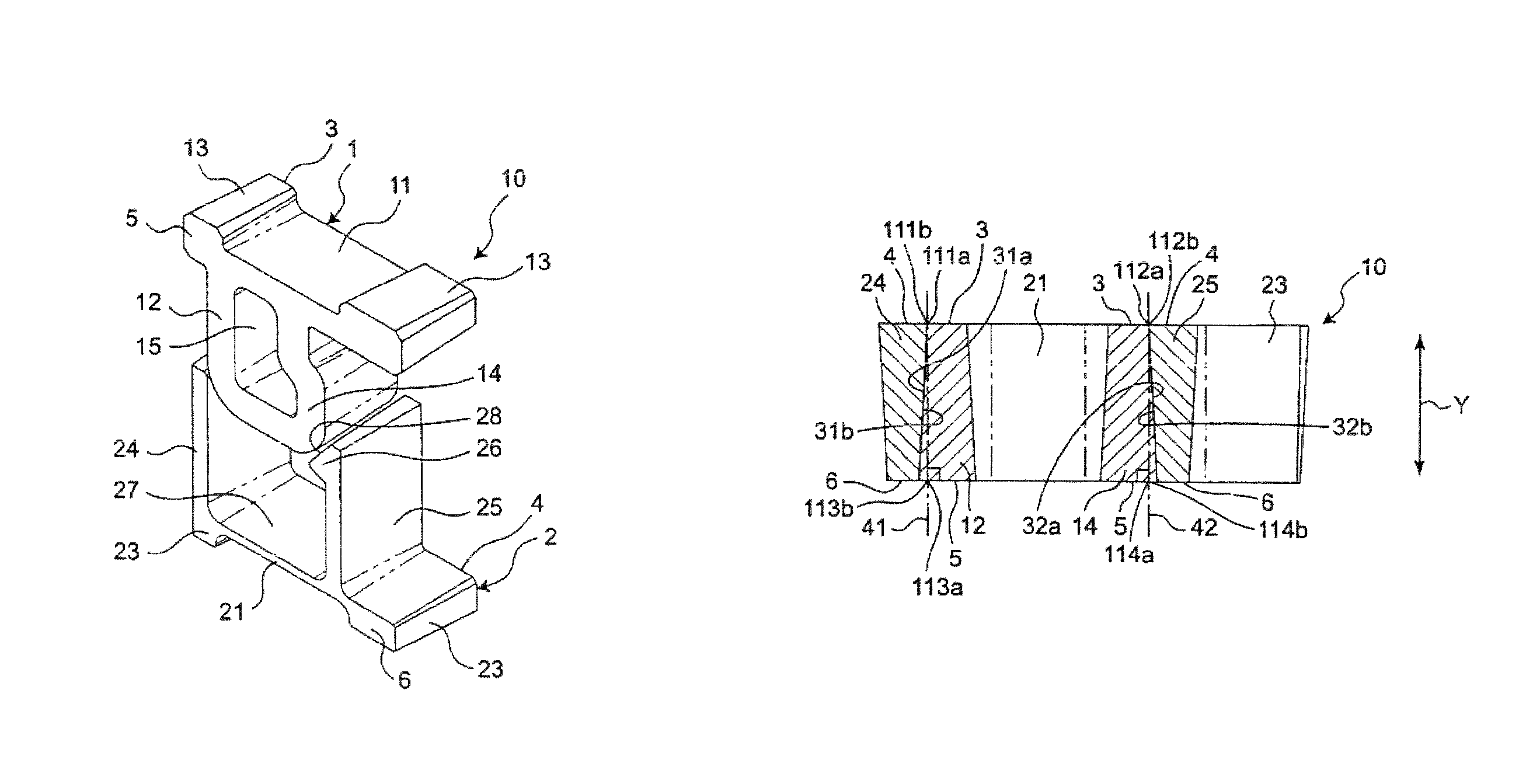
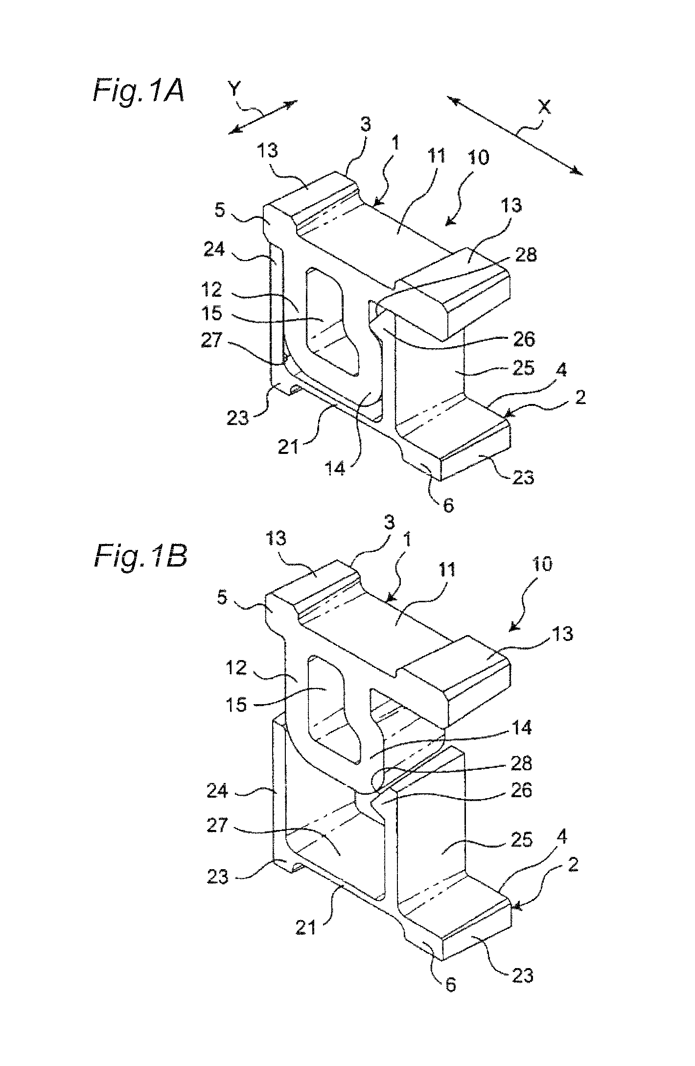
[0054]As shown in FIGS. 1A and 1B, a connecting mechanism generally indicated at 10 according to the first embodiment of the invention has a first contact or male contact 1 and a second contact or female contact 2, both manufactured by electroforming process.

[0055]The contact 1, which is in the form of substantially P-shaped when viewed from its front, has a flat plate portion 11 and a frame-like insertion portion 12 provided on one side of a bottom surface of the flat plate portion 11. The flat plate portion 11 has at its opposite ends upwardly projected soldering portions 13 to be soldered. The insertion portion 12 is substantially U-shaped and has at its one side an outwardly deformed locking projection 14. The male contact 1 has at its substantially center an opening 15 surrounded by the flat plate portion 11 and the insertion portion 12. A first surface 3 and a second surface 5 of the male contact 1, defined by planes orthogonal to the thickness-wise Y-direction of the male con...

second embodiment

[0072]As shown in FIGS. 3A and 3B, a connecting mechanism 50 according to the second embodiment has a male contact (first contact) 51 and a female contact (second contact) 52. Similar to the first embodiment, the male contact 51 and the female contact 52 are manufactured by the electroforming process. According to this embodiment, the male contact 51 and the female contact 52 are formed symmetrically when viewed from front.

[0073]The male contact 51 has a plate-like liner portion 61, a contact portion 62 provided at one end of the linear portion 61, and a soldering portion 63 provided at the opposite end of the linear portion 61. The contact portion 62 is tapered so as to have a substantially triangular configuration when viewed from front. The soldering portion 63 has a substantially rectangular configuration when viewed from front. The linear portion 61 has a width smaller than those of the contact portion 62 and the soldering portion 63.

[0074]The female contact 52 has a base which...


PUM

PropertyMeasurementUnit
taper angleaaaaaaaaaa
angleaaaaaaaaaa
inclined anglesaaaaaaaaaa

Abstract

A connecting mechanism having a male contact and a female contact, each of the male and female contacts having a first surface including at least in part a flat surface portion defined therein, a second surface opposing the first surface, and a contact surface extending between the first surface and the second surface. The contact surface is designed so that, when the first contact and the second contact are electrically connected with each other, the contact surfaces of the first contact and the second contact make a surface contact therebetween that inclines with respect to the flat surface portions of the first and second contacts in a cross section that crosses the first surface, the second surface, and the contact surface.

Description

TECHNICAL FIELD[0001]This invention relates to a connecting mechanism to be incorporated in a connector.BACKGROUND[0002]Conventionally, there has been disclosed a connecting mechanism in, for example, Patent Document 1, which includes a plug connector having a plug contact and a receptacle connector having a receptacle contact. The plug contact and the receptacle contact are designed so that they are brought into contact with each other to make an electrical connection therebetween.PRIOR ART DOCUMENT(S)[0003]Patent Document 1: JP2009-283357(A)[0004]A recent trend of miniaturization of the connector results in a small and low profile connecting mechanism. This necessarily decreases a contact area of the contacts and thereby increases a contact resistance and an amount of heat generated at the contact portions, which eventually reduces an amount of electricity to be fed across the contacts.[0005]Further, the reduction of contact area between the contacts may need an increased force fo...

Claims


Application Information

Patent Timeline
Patent Type & Authority Patents(United States)
IPC IPC(8): H01R24/00H01R13/11H01R12/71H01R24/60H01R13/405H01R33/00H01R12/58H01R43/16B32B3/26H01R13/04
CPCH01R13/405B32B3/266H01R12/58H01R12/71H01R13/04H01R13/11H01R24/60H01R43/16B32B2307/202B32B2307/206B32B2457/00
Inventor HEMMI, YOSHINOBUTERANISHI, HIROTADASAKAI, TAKAHIROKOTAKE, YUKI
Owner ORMON CORP
Why Eureka
Try Eureka