Craniotomy drill

a craniotomy and drill head technology, applied in the field of surgery, can solve the problems of large upper part of the casing, heavy weight of the whole drill head, etc., and achieve the effect of safe, reduced volume and weight, and simple structur

Active Publication Date: 2013-07-11
CHONGQING RUNZE PHARM CO LTD
View PDF13 Cites 8 Cited by
  • Summary
  • Abstract
  • Description
  • Claims
  • Application Information

AI Technical Summary

Benefits of technology

[0015]The present invention has a simple structure with the wall of the accommodating part as the stator housing of the electric motor, such that the volume and the weight are reduced. It is safe in use without the risk of the electric motor sliding out. By utilizing materials and processes of water resistant technology and an integrative design, a relatively good water resistant performance is achieved. When it is necessary to insert the drill transmission rod, the locking sleeve is pressed down. At this moment, the second bugle

Problems solved by technology

This structure has a large-size upper part of the casing and the whole weight of the craniotomy drill is heavy.
After a period of tim

Method used


Image

  • Craniotomy drill
  • Craniotomy drill
  • Craniotomy drill

Examples


Embodiment Construction

[0021]Embodiments of the present invention will now be described, by way of example only, with reference to the accompanying drawings.

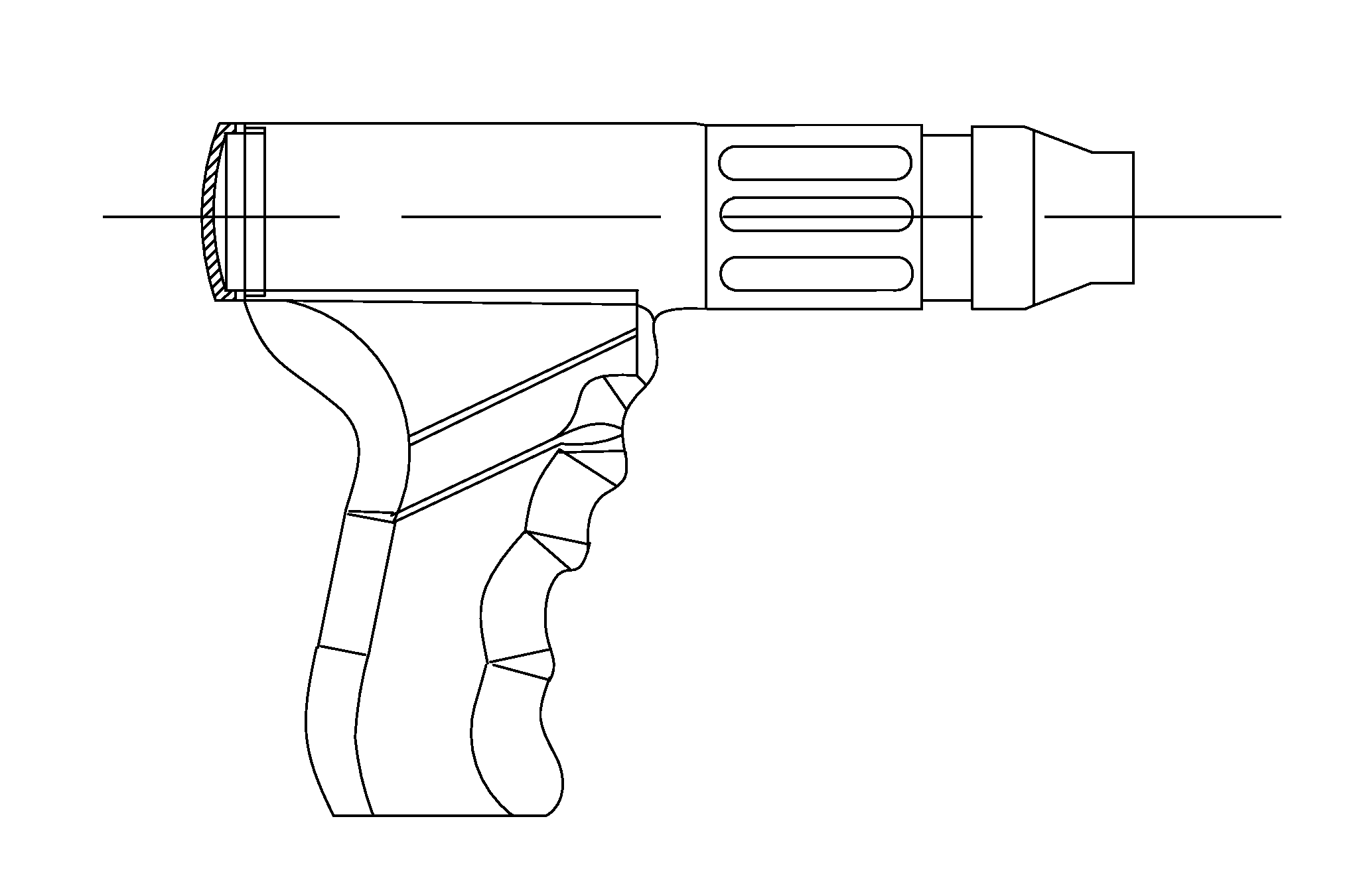
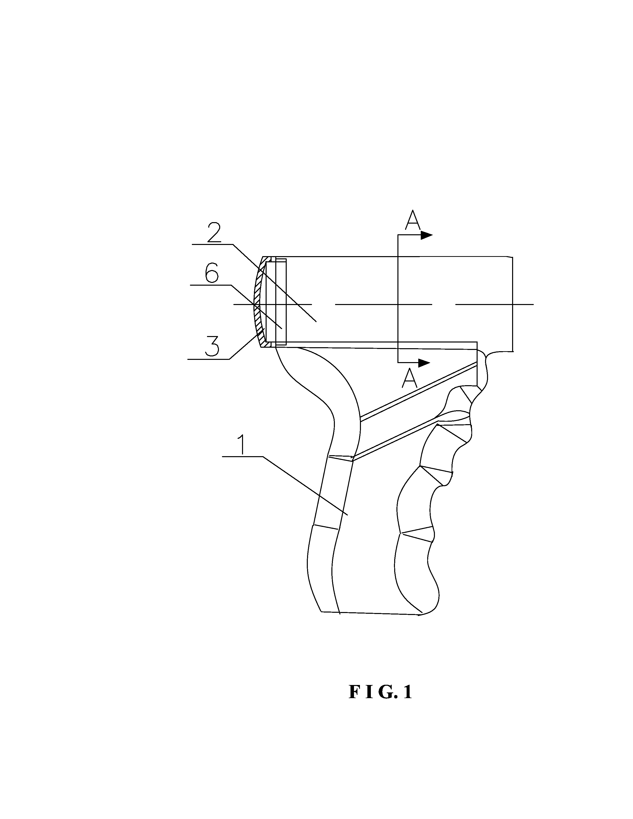
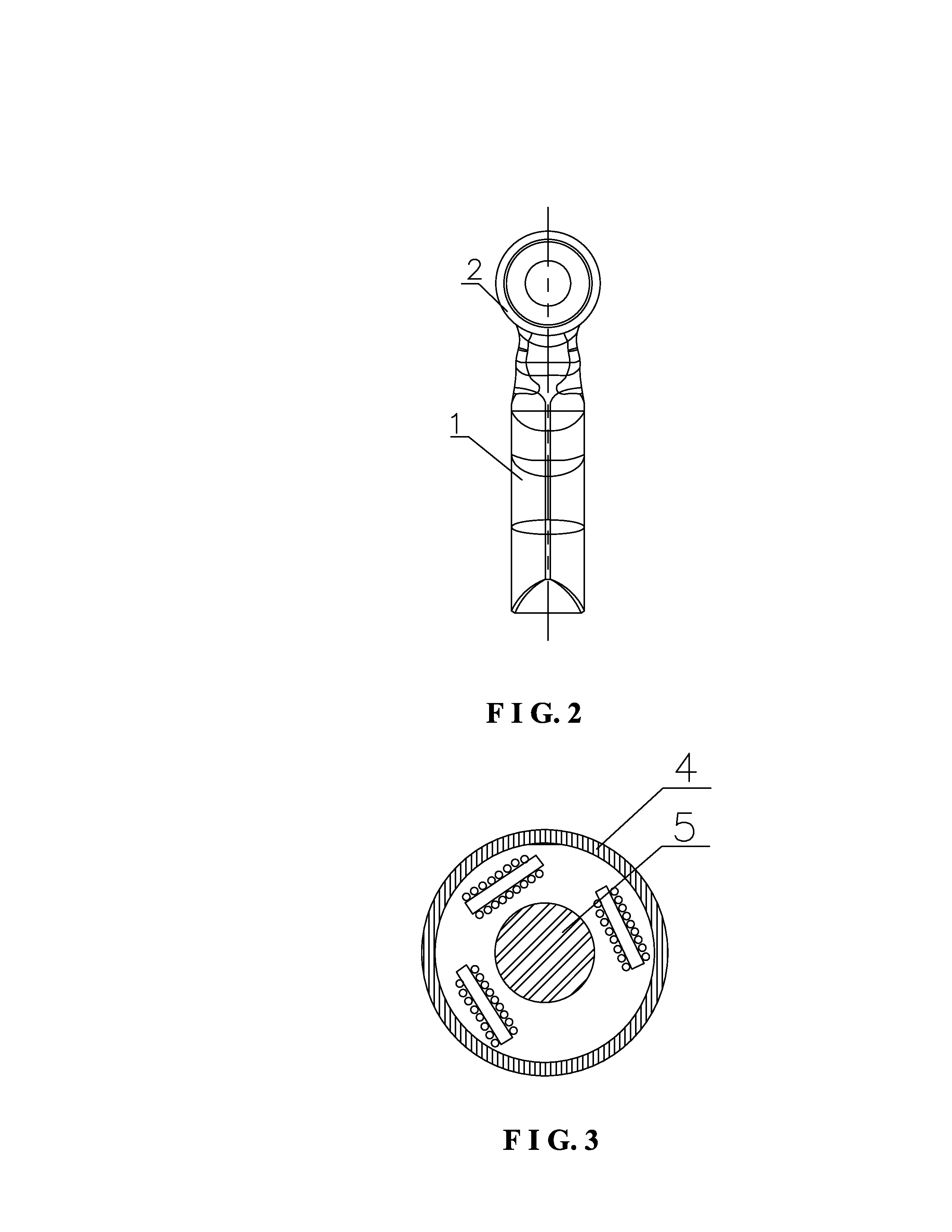
[0022]As shown in FIG. 1 to FIG. 2, a craniotomy drill comprises a main machine, a retarder and a locking seat which are successively threadedly connected. A drill transmission rod connected to an output shaft of the retarder is inserted in the locking seat. The main machine comprises a handle (1) at a lower portion thereof and an accommodating part (2) at an upper portion thereof. A stator and a rotor of a direct current (DC) electric motor are provided inside the accommodating part (2) and a wall (4) of the accommodating part (2) is as a stator housing of the DC electric motor. A rear part of the accommodating part (2) is provided with a stop plate (6) having a hole to divide the accommodating part (2) into two chambers. The stator of the motor is disposed in the front chamber. A rear end cap (3) is threadedly connected to the rear end of the accomm...


PUM


Abstract

A craniotomy drill includes a main machine, a retarder and a locking seat. A drill transmission rod connected to the output shaft of the retarder is inserted in the locking seat. The main machine comprises a handle at the lower portion and an accommodating part at the upper portion, with a stator and a rotor of a DC electric motor being provided inside the accommodating part and a wall of the accommodating part being the stator housing of the DC electric motor. This craniotomy drill has a simple structure with the wall of the accommodating part as the stator housing of the electric motor, such that the volume and the weight are reduced. It is safe in use without the risk of the electric motor sliding out. By utilizing materials and processes of water resistant technology and an integrative design, a relatively good water resistant performance is achieved.

Description

BACKGROUND OF THE INVENTION[0001]1. Field of the Invention[0002]The present invention relates to a bone drill machine for surgery.[0003]2. Description of the Prior Art[0004]During a surgical operation, a craniotomy drill is often used to open a skull. The craniotomy drill comprises a main machine, a retarder, a locking seat and a drill bit. The main machine comprises a handle at a lower part thereof and a casing having a cylindrical accommodating part and a cylindrical electric motor at an upper part thereof. To assemble the craniotomy drill, the electric motor is placed in the chamber of the cylindrical accommodating part at the upper part of the casing, and then the electric motor is secured with screws. This structure has a large-size upper part of the casing and the whole weight of the craniotomy drill is heavy. After a period of time to use, the screws may loosen and the electric motor may slip off from the accommodation room to cause an accident during surgery.[0005]Accordingl...

Claims


Application Information

Patent Timeline
IPC IPC(8): A61B17/16
CPCA61B17/162A61B17/1695A61B17/1628A61B17/1626
Inventor YE, LEIZHOU, JIANFENG, HUALI, FEIZHU, HENGYANGLI, CONGXIAO
Owner CHONGQING RUNZE PHARM CO LTD
Why Eureka
Try Eureka