High power ultrasound wireless transcutaneous energy transfer (us-tet) source

a wireless transcutaneous energy and source technology, applied in the direction of exchanging data chargers, other medical devices, therapy, etc., to achieve the effect of optimizing power transfer and enhancing focusing effects

Inactive Publication Date: 2013-07-11
PIEZO ENERGY TECH
View PDF9 Cites 48 Cited by
  • Summary
  • Abstract
  • Description
  • Claims
  • Application Information

AI Technical Summary

Benefits of technology

[0013]The ultrasound receiver is contained within an implantable case, the external surface of which is completely fabricated of biocompatible material. It may be implanted at a functionally appropriate distance below the skin surface, e.g. from about 10 mm to about 50 mm below the skin surface, or some distance larger, between, or smaller than those distances. The front, flat face of the implant is fixed in the tissue approximately parallel to the front, flat face of the transmitter. In another embodiment, curved faces are used to enhance focusing effects that optimize the power transfer. Within the case are components for wireless communication with the external controller, electronics for converting the ultrasound to electrical power, sensors for monitoring the temperature at various points within the implant, sensors for monitoring and obtaining the optimum conversion efficiency, and output devices to 1) an implanted battery and 2) directly to the implanted MCSS.
[0014]There are two geometrical issues affecting alignment of a transmitter over a receiver in both the electromagnetic and ultrasound methods. The first is lateral translation over the implant, and the second is angular misalignment between the transmitter and receiver. The use of an array transmitter enables compensation for both of these misalignments. The voltage, current and / or power out of the receiver is a signal fed back to the external controller which commands the array transmitter to search for the optimum alignment. In another embodiment, an imaging ultrasound system is added to the transmitter unit to provide the feedback on the depth and orientation of the implanted receiver, thereby assisting alignment.

Problems solved by technology

There are two geometrical issues affecting alignment of a transmitter over a receiver in both the electromagnetic and ultrasound methods.

Method used


Image

  • High power ultrasound wireless transcutaneous energy transfer (us-tet) source
  • High power ultrasound wireless transcutaneous energy transfer (us-tet) source
  • High power ultrasound wireless transcutaneous energy transfer (us-tet) source

Examples


Embodiment Construction

Overall Assembly

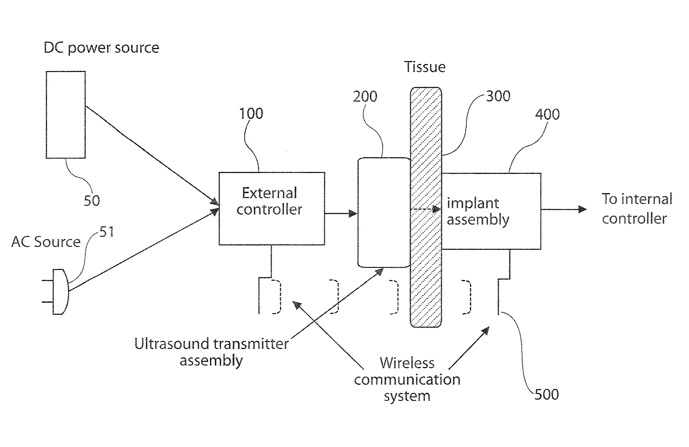
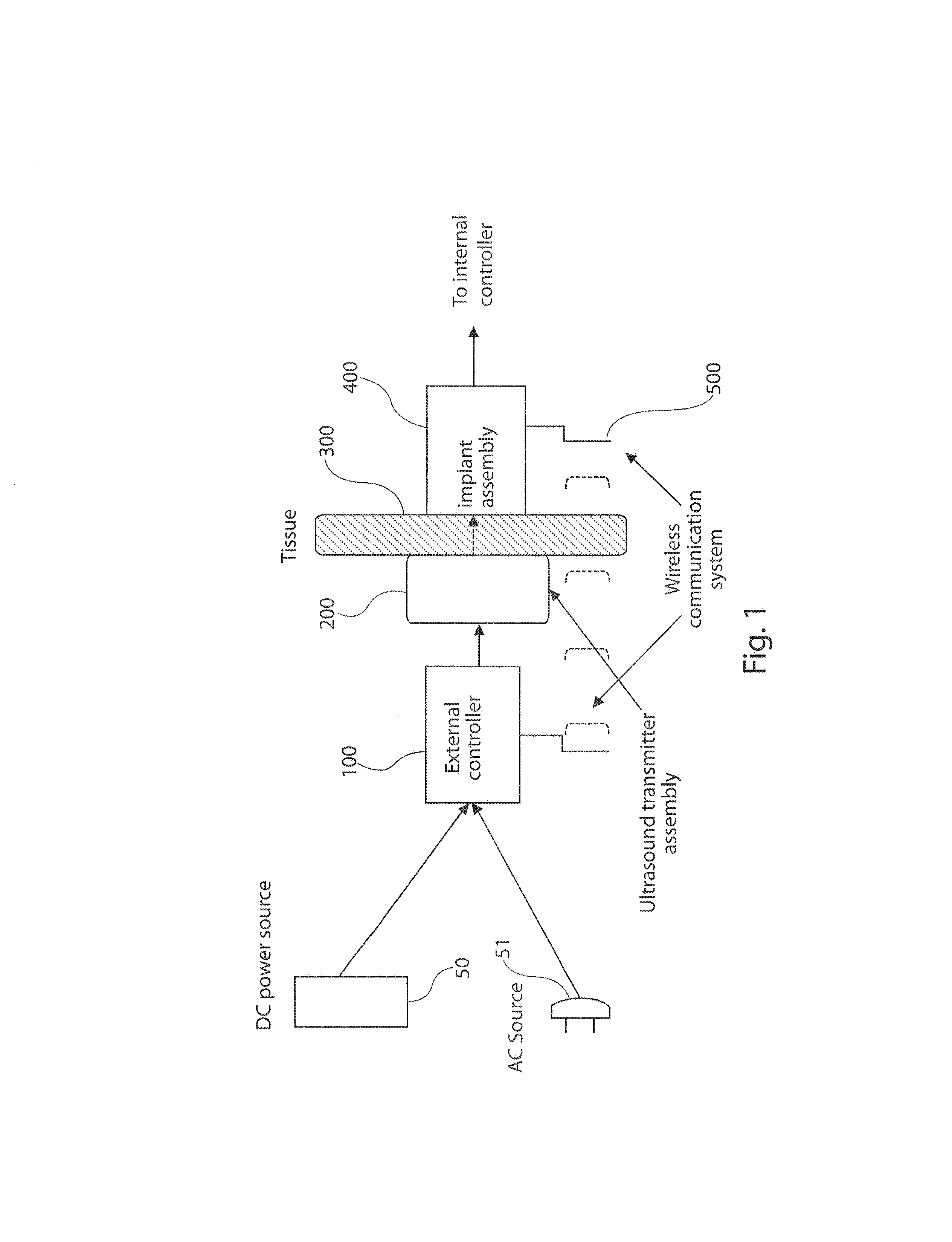
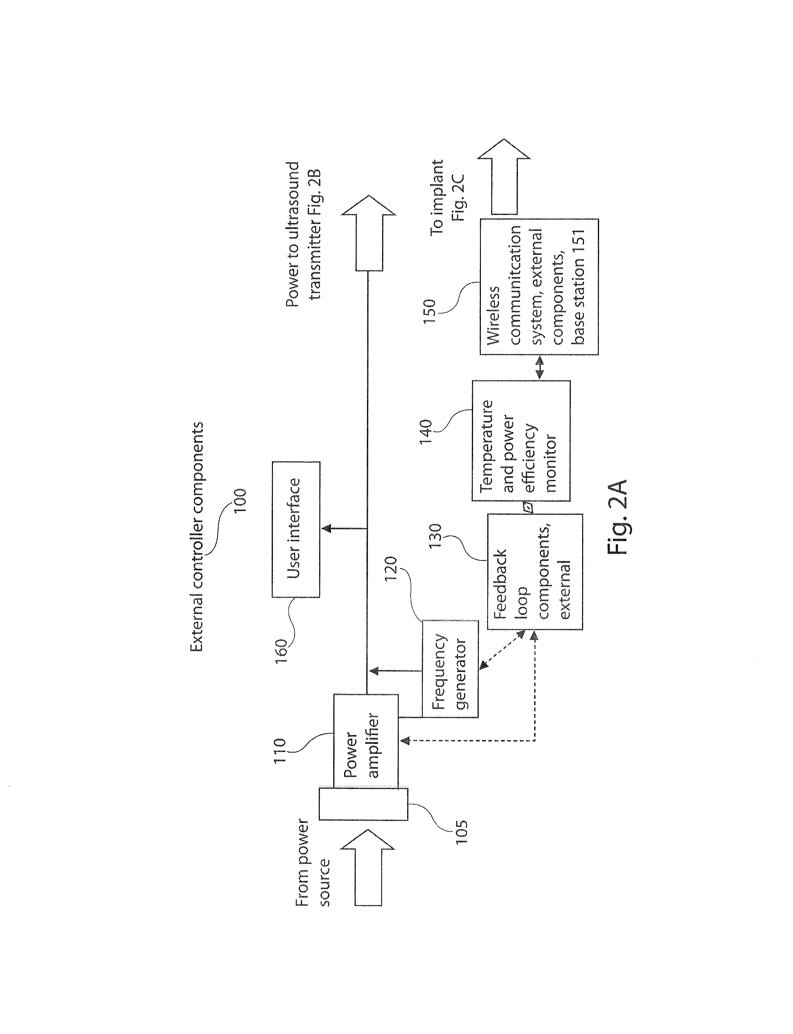
[0045]FIG. 1 is an overall block diagram of an US-TET system in accordance with the present invention. FIGS. 2A, 2B, and 2C are block diagrams the items within the external controller 100, the transmitter assembly 200, and the implant assembly 400. Referring to FIG. 1, two possible sources of power can operate the system. They are either a direct current (DC) power supply 50 such as a battery, typically worn by the patient, or a conventional room alternating current (AC) source 51. Circuitry within the external controller 100 determines whether the input power is low frequency AC. If so, it proceeds through a DC converter and then through circuitry 120 which converts it to high frequency ultrasound. The external controller 100 determines the level of input power and frequency of the ultrasound. These can be operated in two modes, manually and automatically, the latter via a feedback loop 130 and 450 made possible by the wireless communication system 500, which has ex...


PUM


Abstract

A bio-implantable energy capture and storage assembly is provided. The assembly includes an acoustic energy transmitter and an acoustic energy receiver. The acoustic energy receiver also functions as an energy converter for converting acoustic energy to electrical energy. An electrical energy storage device is connected to the energy converter, and is contained within a bio-compatible implant for implantation into tissue. The acoustic energy transmitter is separate from the implant, and comprises a substantially 2-dimensional array of transmitters.

Description

CROSS REFERENCE TO RELATED APPLICATION[0001]This application claims priority from U.S. Provisional Application Ser. No. 61 / 585,101, filed Jan. 10, 2012, the contents of which are incorporated herein in their entireties.STATEMENT REGARDING FEDERALLY SPONSORED RESEARCH OR DEVELOPMENT[0002]This invention was made in part with Government support under grants number 1R43EB007421-01A1 and R44EB007421 awarded by the National Institutes of Health (NIH). The Government has certain rights in the invention.BACKGROUND OF THE INVENTION[0003]The present invention relates to systems for powering implanted devices. The invention has particular utility for systems for powering implanted devices such as heart-assist devices and will be described in connection with such utility, although other utilities are contemplated.[0004]The present invention addresses a critical barrier to a major increase in the availability of heart assist-devices to patients in need: the present method of providing power to t...

Claims


Application Information

Patent Timeline
Patent Type & Authority Applications(United States)
IPC IPC(8): A61N1/378A61M60/122A61M60/538A61M60/585A61M60/875
CPCA61N1/3787A61N1/37217H02J17/00A61M1/127H02J7/00A61M2205/8237H02J50/15H02J50/90A61M60/538A61M60/875A61M60/585H02J2310/23H02J7/00034
Inventor RADZIEMSKI, LEON J.SINGH MAKIN, INDER RAJ
Owner PIEZO ENERGY TECH
Why Eureka
Try Eureka