Image sensor unit, image reading apparatus, image forming apparatus, and manufacturing method

a technology of image reading apparatus and manufacturing method, which is applied in the direction of metal working apparatus, chemistry apparatus and processes, manufacturing tools, etc., can solve the problem of significantly difficult work of accurately positioning the rod-lens array inserted to the thin groove of the fram

Active Publication Date: 2013-07-18
CANON COMPONENTS INC
View PDF6 Cites 28 Cited by
  • Summary
  • Abstract
  • Description
  • Claims
  • Application Information

AI Technical Summary

Benefits of technology

[0010]The present invention has been made in view of the problem described above, and an object of the present invention is to accurately dispose a plurality of rod-lens arrays in disposing a plurality of rod-lens arrays in a line in the main-scan direction.

Problems solved by technology

However, there is a problem that work of accurately positioning the rod-lens arrays inserted to thin grooves of frames is significantly difficult.

Method used


Image

  • Image sensor unit, image reading apparatus, image forming apparatus, and manufacturing method
  • Image sensor unit, image reading apparatus, image forming apparatus, and manufacturing method
  • Image sensor unit, image reading apparatus, image forming apparatus, and manufacturing method

Examples


first embodiment

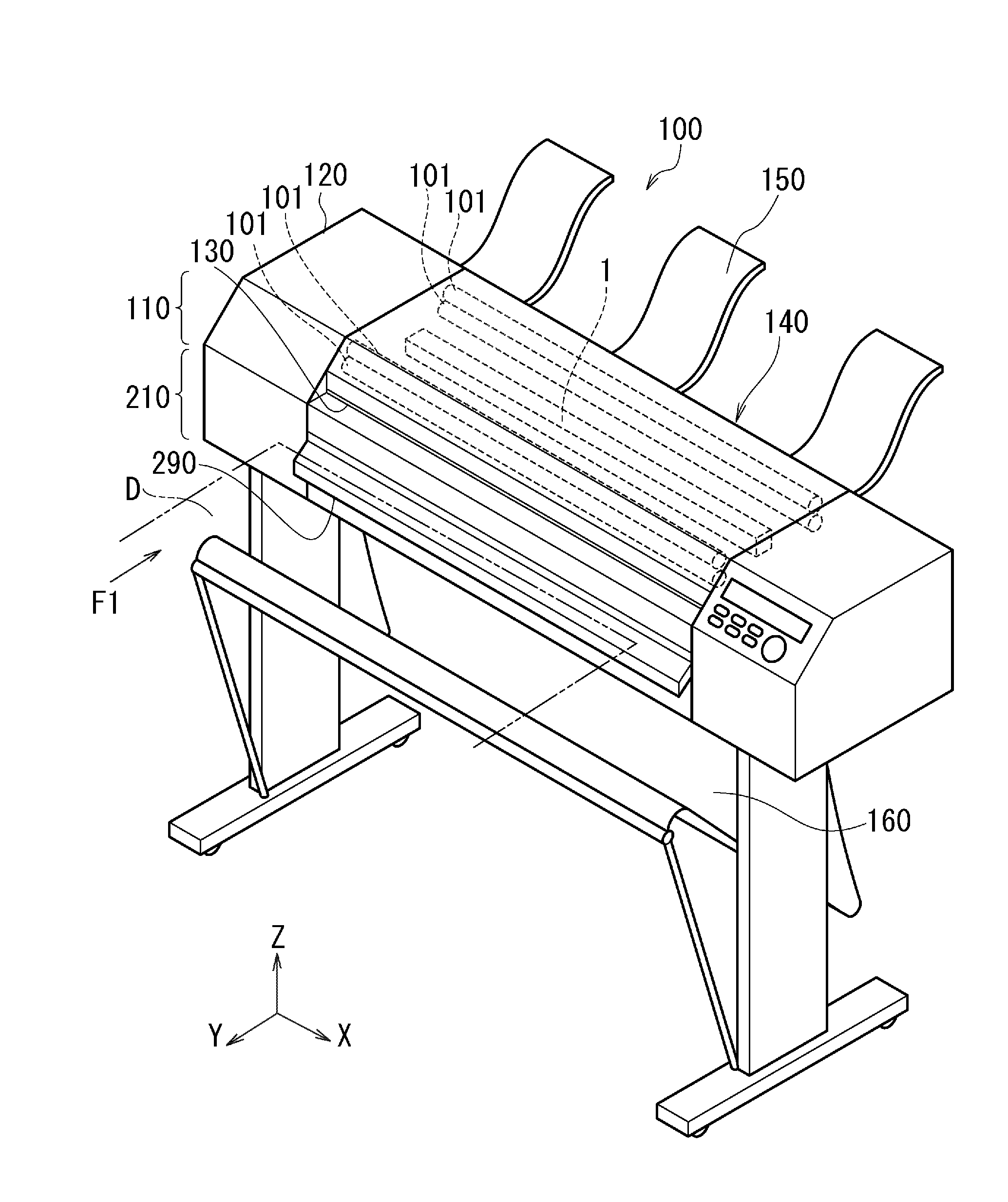
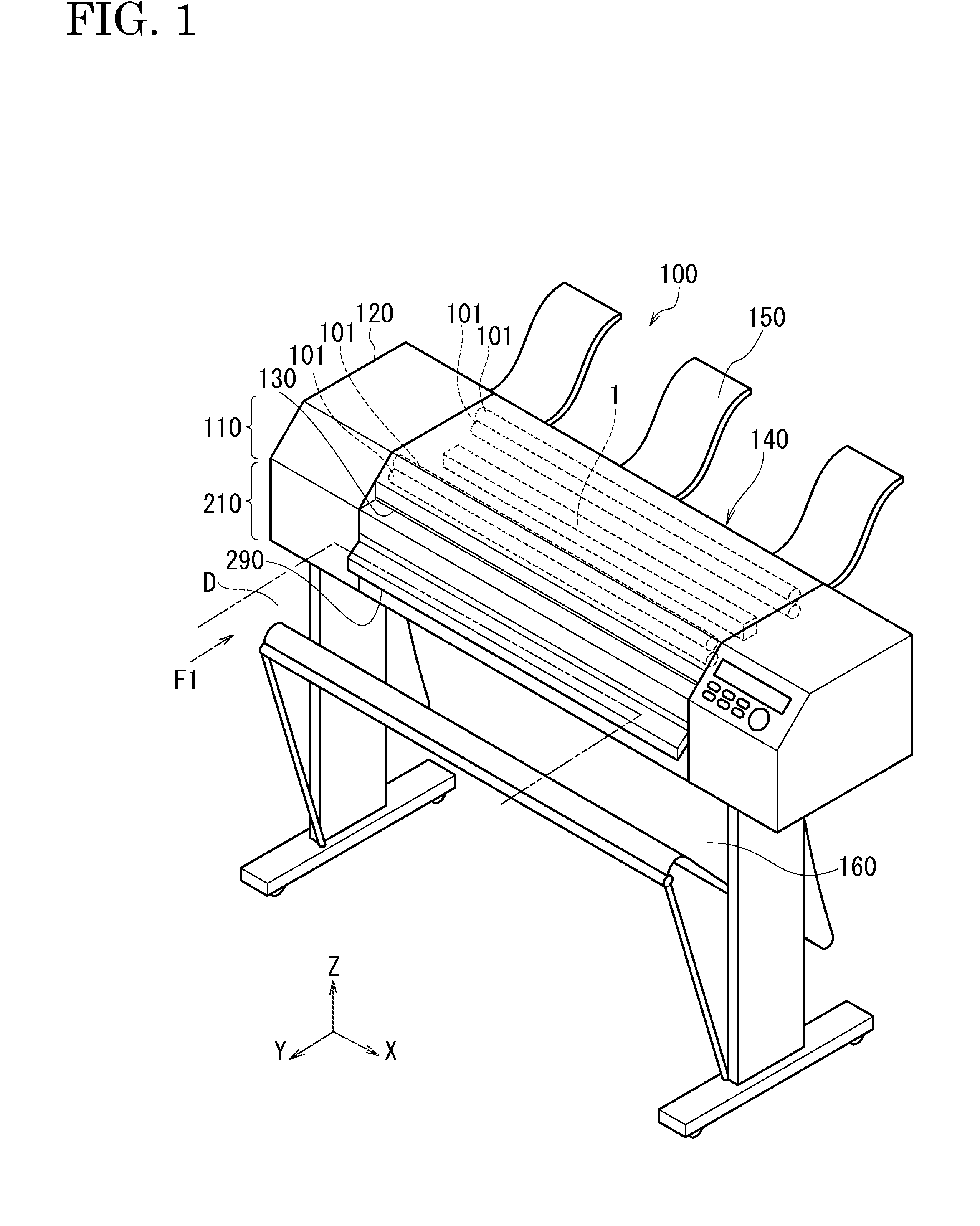
[0039]Constituent members of the image sensor unit 1 will be described with reference to FIGS. 3 to 5.

[0040]FIG. 3 is a sectional view illustrating a configuration of the image reading portion 110 in the MFP 100 including the image sensor unit 1 according to a first embodiment. FIG. 4 is a schematic exploded perspective view of the image sensor unit 1. FIG. 5 is a schematic exploded perspective view of part of the image sensor unit 1.

[0041]The image sensor unit 1 includes a cover glass 2 as a transparent member, light sources 3 (3a and 3b), a rod-lens array 20 as a light condenser, a sensor substrate 6, the sensor chip 7 as a photoelectric conversion element, a lower cover 8 as a cover member, a frame body 80 as a supporting body that house the constituent elements, a side plate member 50, a cover holding member 55, and the like. Among the constituent elements, the cover glass 2, the frame body 80, and the lower cover 8 are formed long in the main-scan direction according to the rea...

second embodiment

[0091]An image sensor unit 10 according to a second embodiment will be described with reference to FIG. 11. FIG. 11 is a sectional view illustrating a configuration of the image reading portion 110 in the MFP 100 including the image-sensor unit 10 according to the second embodiment.

[0092]Compared to the first embodiment, a method of fixing the sensor substrate 6 to the frame body 80 and a method of fixing the lower cover 8 to the frame body 80 are different in the image sensor unit 10 of the present embodiment. The other configurations are similar to those of the first embodiment. The same reference numerals are provided, and the description will not be repeated.

[0093]The method of fixing the sensor substrate 6 to the frame body 80 will be described. As shown in FIG. 11, the sensor substrate 6 of the present embodiment is just fixed, through the screws 71, to the screw holes 45 formed at predetermined intervals in the main-scan direction of the first frame 30a and is not fixed to th...


PUM

PropertyMeasurementUnit
transparentaaaaaaaaaa
elasticaaaaaaaaaa
adhesiveaaaaaaaaaa

Abstract

An image sensor unit includes: sensor substrates on which a plurality of sensor chips are mounted; rod-lens arrays that focus light from an original on the sensor substrates; and a frame body that houses the plurality of sensor substrates and the plurality of rod-lens arrays. The frame body is divided into a first frame and a second frame. A side surface of the rod-lens array in a sub-scan direction is fixed only by the first frame, and the plurality of rod-lens arrays are arranged in the main-scan direction.

Description

CROSS-REFERENCE TO RELATED APPLICATIONS[0001]This application is based upon and claims the benefit of priority of the prior Japanese Patent Application No. 2012-007460, filed on Jan. 17, 2012, and the Japanese Patent Application No. 2013-002491, filed on Jan. 10, 2013, the entire contents of which are incorporated herein by reference.BACKGROUND OF THE INVENTION[0002]1. Field of the Invention[0003]The present invention relates to an image sensor unit, an image reading apparatus, an image forming apparatus, a manufacturing method of the image sensor unit, a manufacturing method of the image reading apparatus, and a manufacturing method of the image forming apparatus. Particularly, the present invention relates to an image sensor unit that reads large originals and the like, an image reading apparatus, an image forming apparatus, a manufacturing method of the image sensor unit, a manufacturing method of the image reading apparatus, and a manufacturing method of the image forming appara...

Claims


Application Information

Patent Timeline
Patent Type & Authority Applications(United States)
IPC IPC(8): H01L31/18H01L31/0232
CPCH04N1/193H01L31/0232H01L31/18H04N1/192H04N1/1931Y10T29/49826H04N1/1933H04N1/1934H04N1/1935H04N1/1938Y10T156/1089H04N1/1932Y10T29/49286
Inventor SUGIYAMA, TAKESHI
Owner CANON COMPONENTS INC
Why Eureka
Try Eureka