Wire-harness routing device

Active Publication Date: 2013-07-18
YAZAKI CORP
View PDF5 Cites 6 Cited by
  • Summary
  • Abstract
  • Description
  • Claims
  • Application Information

AI Technical Summary

Benefits of technology

[0018]According to the present invention, as mentioned above, the wiring-harness routing device includes two wiring harnesses, and the protector having the pair of wiring-harness hold members positioned in the rail and holding the two wiring harnesses to be arranged in parallel to each other along the widthwise direction of the rail; the lead member arranged between the pair of wiring-harness hold members, and passing electric wires of the two wiring harnesses therethrough, and extending with a cylindrical shape along the height direction of the rail so as to pass through the slit and be led to the outside of the rail; and the mount member attached at the support body so as to have the gap allowing motion in the widthwise direction of the rail. Thereby, even if the support body slides with the rattle motion along the widthwise direction of the rail, the protector can move about the support body in the widthwise direction, so as to limit motion of the protector in the widthwise direction about the rail. Thus, the protector can slide against influence of rattle motion of the support body in the widthwise direction. When the support body has tolerance of a dimension in the widthwise direction of the rail, the tolerance of the dimension can be absorbed by the protector moving in the widthwise direction against the support body. Therefore, the room for receiving the protector in the rail, that is the room for receiving the wiring harness, can be increased. Thus, the room for receiving the protector can be increased, so that the wiring-harness routing device, in which a large number of electric wires can be routed, can be provide.
[0019]According to the present invention, the support body includes the pair of projections arranged at an interva

Problems solved by technology

Thereby, there is a problem that a number of electric wires able to be routed therein is small.
Thereby, a room for receiving the protector in the rail 2 is limited about a space, so that there is

Method used


Image

  • Wire-harness routing device
  • Wire-harness routing device
  • Wire-harness routing device

Examples


Example

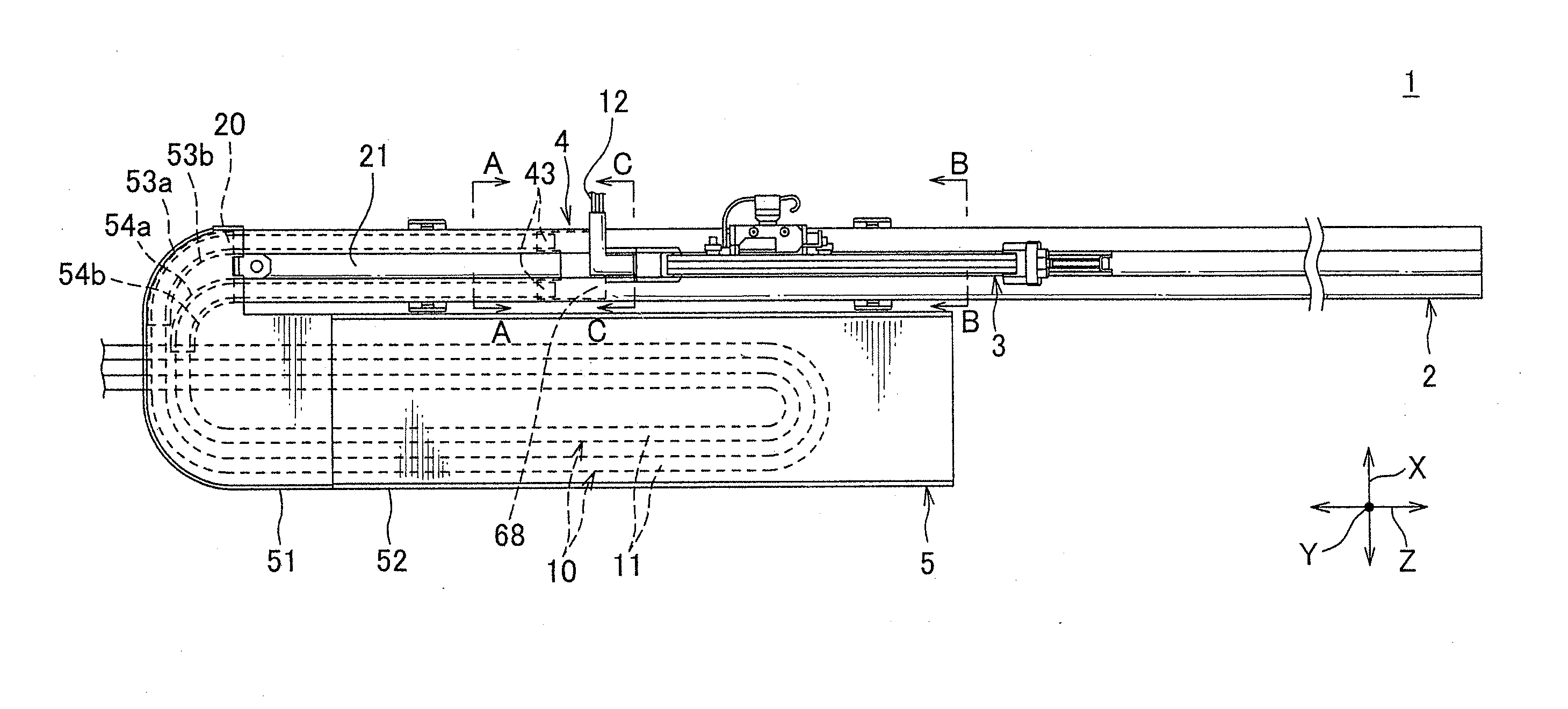
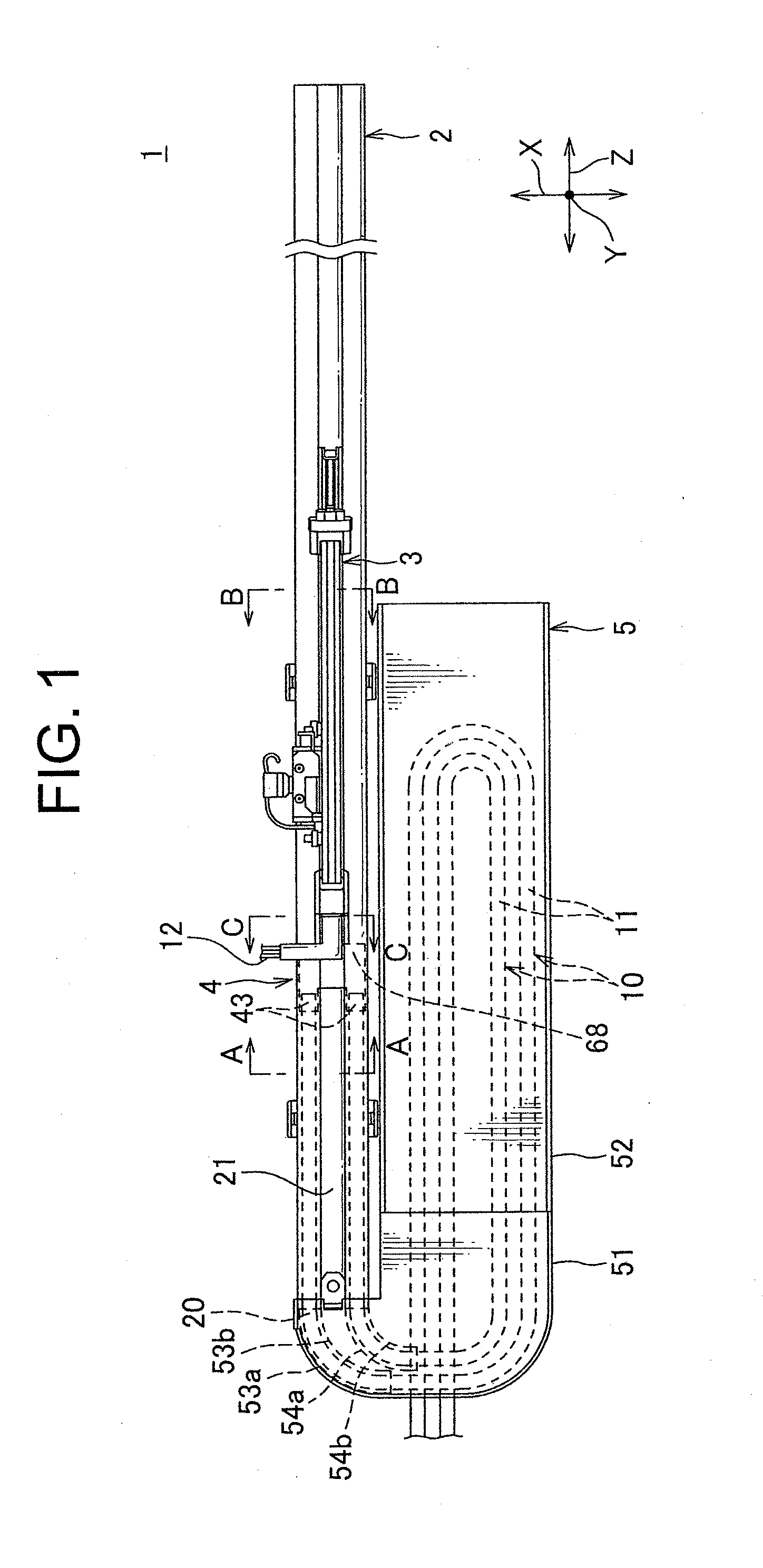
[0043]A wiring-harness routing device of a preferable embodiment according to the present invention is described with reference to FIGS. 1-18.

[0044]The wiring-harness routing device 1 is for routing two wiring harnesses 10 between a floor of a passenger compartment as a car body of a car and a seat arranged slidably about the floor as a slide body. The seat includes an electronic device, for example, a seat sensor sensing sitting of a passenger at the seat and a seat-belt sensor sensing fastening a seat belt for the passenger sitting on the seat.

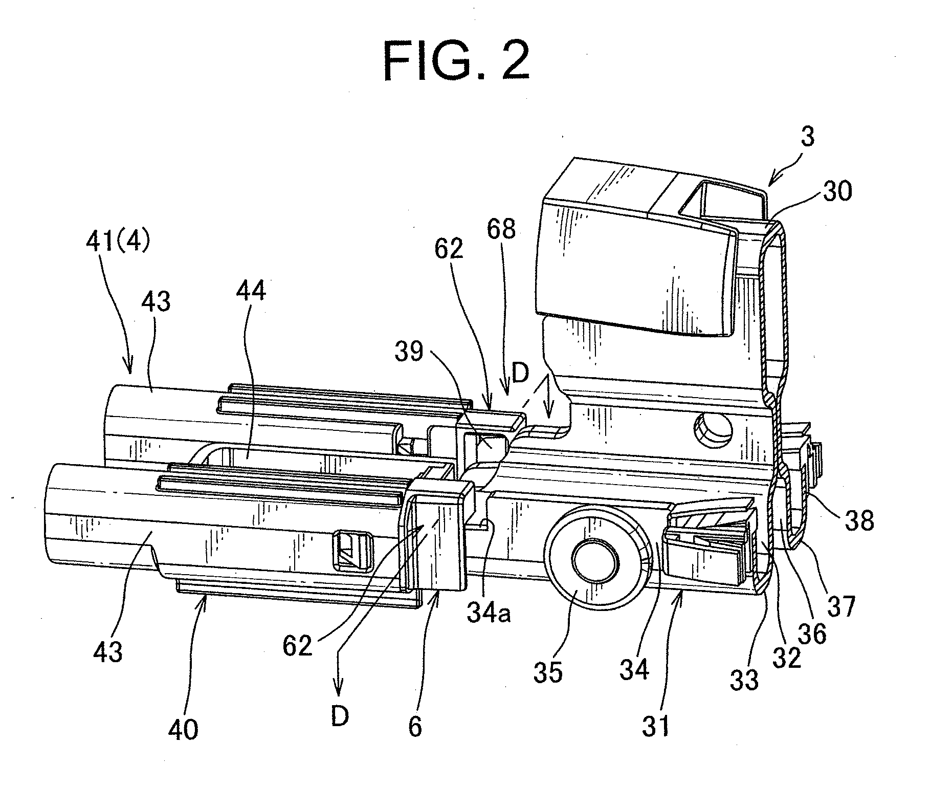
[0045]The wiring-harness routing device 1 includes the two wiring harnesses 10, a long cylindrical shape rail 2 fixed at the floor, a support body 3 provided slidably at the rail 2 and supporting the seat, a protector 4 sliding correspondingly to the support body 3 and guiding the two wiring harnesses 10 toward the seat and a receiving section 5 receiving an extra length of the two wiring harnesses 10.

[0046]An arrow Z in FIG. 1 indicates a s...


PUM


Abstract

The wiring-harness routing device 1 includes two wiring harness 10, a support body 3 mounted slidably at a rail 2 and supporting a seat, and a protector 4 sliding interlockingly with the support body 3 and leading the two wiring harnesses 10 to the seat. The protector 4 includes a pair of wiring-harness hold portion 43 holding the two wiring harnesses 10 led through an opening 20 into the rail 2 to be arranged in parallel; portion arranged between the pair of wiring-harness hold portions 43, and passing the two wiring harnesses 10 therethrough, and extending with a cylindrical shape so as to go through the slit and be led to an outside of the rail 2; and a mount portion 68 attached at the support body 3 so as to have a gap allowing motion in the widthwise direction of the rail 2.

Description

TECHNICAL FIELD[0001]This invention relates to a wiring-harness routing device, which routes a wiring harness between a car body, such as a floor of a car, and a slide body, such as a seat provided slidably about the car body.BACKGROUND ART[0002]A seat as a slide body may be provided slidably about a floor of a passenger room as a car body. At the seat, an electronic device such as a seat sensor sensing seating of a passenger is mounted. Therefore, various wiring-harness routing device routing a wiring harness between the floor and the seat is used for connecting the electronic device provide at the seat and the electronic device fixed at the floor in the car in which the slidable seat is provided (see Patent document 1).[0003]A wiring-harness routing device 201 shown in FIGS. 19-21 was invented by the present inventors and filed to Japan Patent Office (Application number 2009-99100). The wiring-harness routing device 201 in patent pending routes a wiring harness 10 between a floor ...

Claims


Application Information

Patent Timeline
IPC IPC(8): B60R16/02
CPCB60R16/0215B60R16/027H02G11/00
Inventor TERADA, TOMOYASUSEKINO, TSUKASAIWAHARA, SEIJIYOKOYAMA, MASAKIKATO, SHINJISATO, FUMIAKISAKAKIBARA, YASUHIROTAKENAKA, YASUNORIARAKI, TOSHIOISHIMARU, RYUYAKAISAKU, TETSUYA
Owner YAZAKI CORP
Why Eureka
Try Eureka