Lidar Imager

Active Publication Date: 2013-07-18
IEE INT ELECTRONICS & ENG SA
View PDF7 Cites 39 Cited by
  • Summary
  • Abstract
  • Description
  • Claims
  • Application Information

AI Technical Summary

Benefits of technology

[0008]Thus, by changing only the holograms displayed by the SLM (and timing of the measurements), one is able to cover a large range of different applications or modes of operation, from ones requiring a very fast frame rate at low resolution, to ones requiring a high resolution at a low frame-rate. It is possible to combine different modes of operation, by defining, e.g., areas of interest in the scene where a high resolution at a high frame rate is required, while for the rest of the scene only rough measurements are sufficient, at low frame rates and/or low resolution. The system could also be configured switch, on demand or upon occurrence of a triggering event, from a “standby” mode with low frame rate and/or low resolution, to a full-operation mode with high frame rate and/or high resolution.
[0009]As will be appreciated, the SLM can be a reflective or a transmissive SLM. The SLM may e.g. comprise a (transmissive) ferroelectric liquid crystal (FLC) panel or a (reflective) FLC on silicon (FLCoS). Commercially available FLCoS panels have up to 1280×1024 pixels (reconfigurable elements). Their response time of is less than 100 μs (which makes it possible to image a scene with 100×100 pixels at a frame rate of 1 Hz, or with 10×10 pixels at a frame rate of 100 Hz). In research papers, FLC cells with response times<10 μs are presented. Alternatively the spatial light modulator could comprise a digital micromirror device, i.e. a chip having on its surface a rectangular array of several hundred thousand pivotable microscopic mirrors. Other technologies could be used for the SLM, such as e.g. a dynamically a

Problems solved by technology

However, FM lidar systems suffer from the limited frequency modulation capabilities of current laser diodes.
Current systems of both categories typically suffer from the disadvantage that they are cannot easi

Method used


Image

  • Lidar Imager
  • Lidar Imager
  • Lidar Imager

Examples


Embodiment Construction

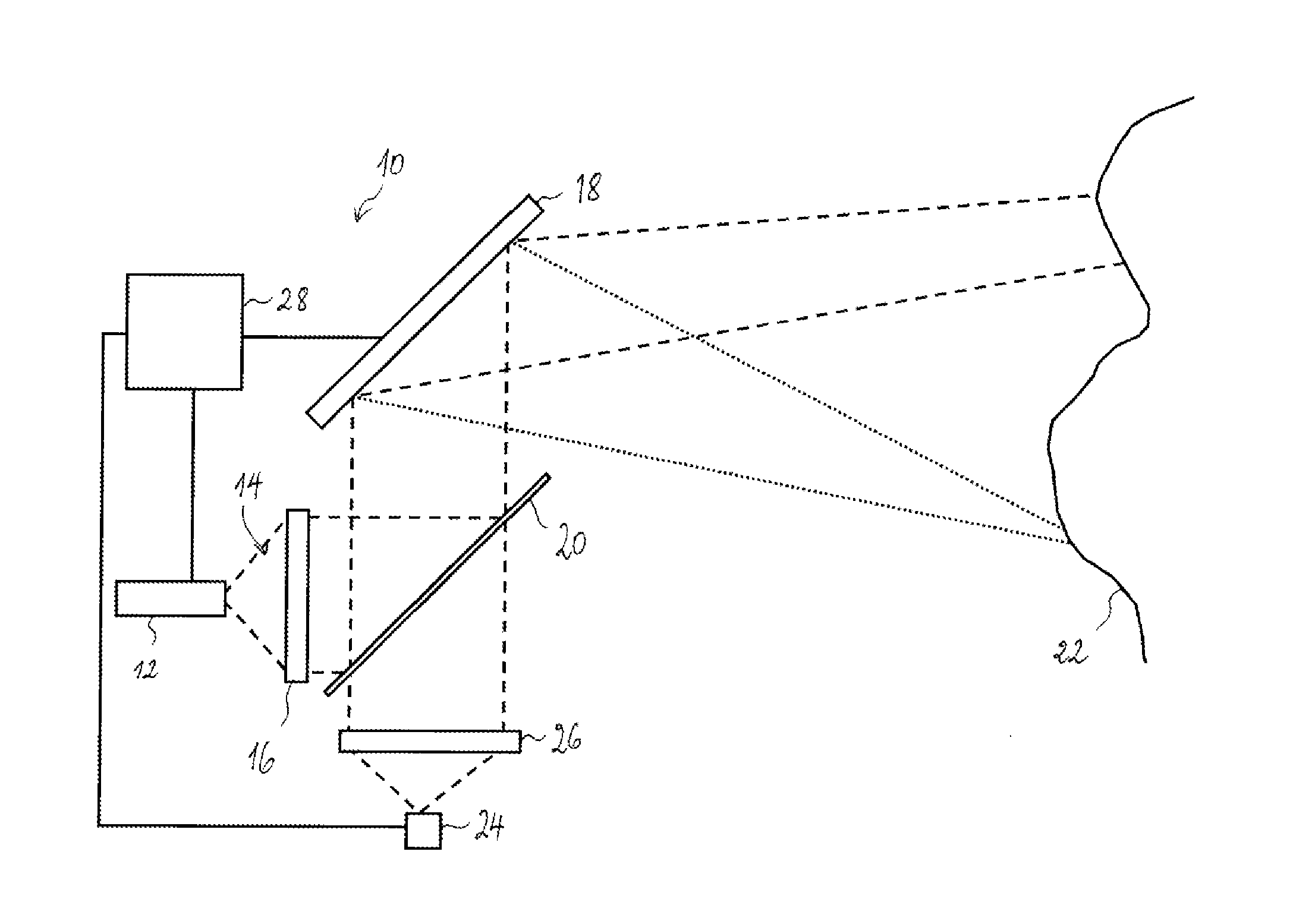
[0021]A first example of a lidar imager 10 according to the invention is shown in FIG. 1. The lidar imager comprises a light source 12 (e.g. a laser), which emits a light beam 14 with sufficient coherence length. The light beam 14 is shaped (collimated) by optics 16 (one or more lenses and / or mirrors). The emitted light beam 14 is incident on a reflective SLM 18 after passing through a beam splitter 20, which separates the emission and reception light paths. In operation, the SLM displays a sequence of holograms that shape the light beam 14 and redirect it into different parts of the scene 22. When the light beam hits an obstacle in the scene, a part of the light is reflected to the lidar image on the light path in opposite direction. The reflected light is deflected by the SLM 18 and focused on a photodetector 24 by optics 26 after passing through the beam splitter 20.

[0022]A control unit 28 (e.g. a microprocessor, an application-specific integrated circuit, a field-programmable ga...


PUM


Abstract

A lidar imager for acquiring a range image of a scene comprises a light source for emitting a light beam, a scanning device for scanning the light beam across the scene and a light sensor for receiving light reflected from the scene. The scanning device comprises a spatial light modulator (SLM) configured to display holograms that deflect the light beam into different directions within the scene to be imaged.

Description

TECHNICAL FIELD[0001]The present invention generally relates to range imaging, i.e. creation of a pixel image of a scene wherein each pixel represents the distance from the imager to the corresponding point in the scene. The present invention specifically relates to a scanning lidar imager.BACKGROUND ART[0002]A known approach to three-dimensional vision uses the “time-of-flight” measurement principle. The range (distance) from the imaging apparatus to a point in the scene is measured by timing of the return of a pulse of light projected onto that point. Lidar systems transmit a modulated light beam into the scene and compare the modulation of the transmitted and returned signal to determine range. For instance, coherent frequency modulator (FM) lidar incorporates frequency modulation / mixing to determine range. However, FM lidar systems suffer from the limited frequency modulation capabilities of current laser diodes. Phase shift (AM) lidar is a preferred approach that correlates the...

Claims


Application Information

Patent Timeline
IPC IPC(8): G01S17/89
CPCG01S7/4811G01S7/4817G02B26/106G01S17/89G01S17/88
Inventor KAISER, JEAN-LUC
Owner IEE INT ELECTRONICS & ENG SA
Why Eureka
Try Eureka