Electrodynamic speaker and method for manufacturing the same

a technology of electrodynamic speaker and manufacturing method, which is applied in the direction of electrical transducer, earpiece/earphone attachment, transducer details, etc., can solve the problems of speaker not being able to be downsized, small electrodynamic speaker has a disadvantage, etc., and achieves the reduction of the number of steps of manufacturing electrodynamic speaker, the reduction of the number of steps of forming tinsel wire to be connected to the voice coil, and the effect of reducing the number of steps

Inactive Publication Date: 2013-07-18
ONKYO KK
View PDF5 Cites 10 Cited by
  • Summary
  • Abstract
  • Description
  • Claims
  • Application Information

AI Technical Summary

Benefits of technology

[0021]In a method for manufacturing the electrodynamic speaker according to the present invention, since the frame includes the void for dividing the approximately annular edge mounting section as described, when the vibration system including the tinsel wire preliminarily processed in advance is moved from one side to the other side of the substrate of the frame so as to be placed on a predetermined position, the middle portion of the tinsel wire is allowed to easily pass through the void of the frame or the window section communicatively connecting to the void. As a result, the number of steps of manufacturing the electrodynamic speaker can be reduced. That is to say, since the step of putting a front end of the tinsel wire into the window section below the edge mounting section that requires a considerable time is replaced by an easy step of simply allowing the middle portion of the tinsel wire through the void of the edge mounting section, the number of steps of forming the tinsel wire to be connected to the voice coil so as to connect it to the terminal can be reduced.
[0022]Further, the edge of the electrodynamic speaker may include an inner periphery fixing section to be coupled to an outer peripheral end of the diaphragm, an outer periphery fixing section to be fixed to the edge mounting section of the frame, and a support movable section for coupling the inner periphery fixing section and the outer periphery fixing section in a vibration-enabled manner. The outer periphery fixing section may have a protrusion on a position corresponding to the void of the edge mounting section, and the protrusion to be entirely or partially held in the void may include a tinsel wire fixing section for fixing the middle portion of the tinsel wire. When the outer periphery fixing section corresponding to a gasket for mounting the edge to the frame

Problems solved by technology

In particularly small or elongated (rectangular, oval (including an oblong shape and a track shape) electrodynamic speakers, since a space on a speaker diaphragm rear surface where a tinsel wire (or lead wire) for supplying an audio signal current to a voice coil is arranged is narrow, there is a problem that the tinsel wire contacts with the diaphragm or the frame and thus a noise is easily generated.
Small electrodynamic speakers have a disadvantage because of various reasons such that when an edge or a damper for supporting a vibration system including a speaker diaphragm is to be provided, the tinsel wire contact with them more easily and thus the speakers cannot be downsized.
However, in electrodynamic speakers, in order to solve the above problem,

Method used


Image

  • Electrodynamic speaker and method for manufacturing the same
  • Electrodynamic speaker and method for manufacturing the same
  • Electrodynamic speaker and method for manufacturing the same

Examples


Embodiment Construction

[0030]An electrodynamic speaker and a manufacturing method for the speaker according to preferred embodiments of the present invention will be described below, but the present invention is not limited to these embodiments.

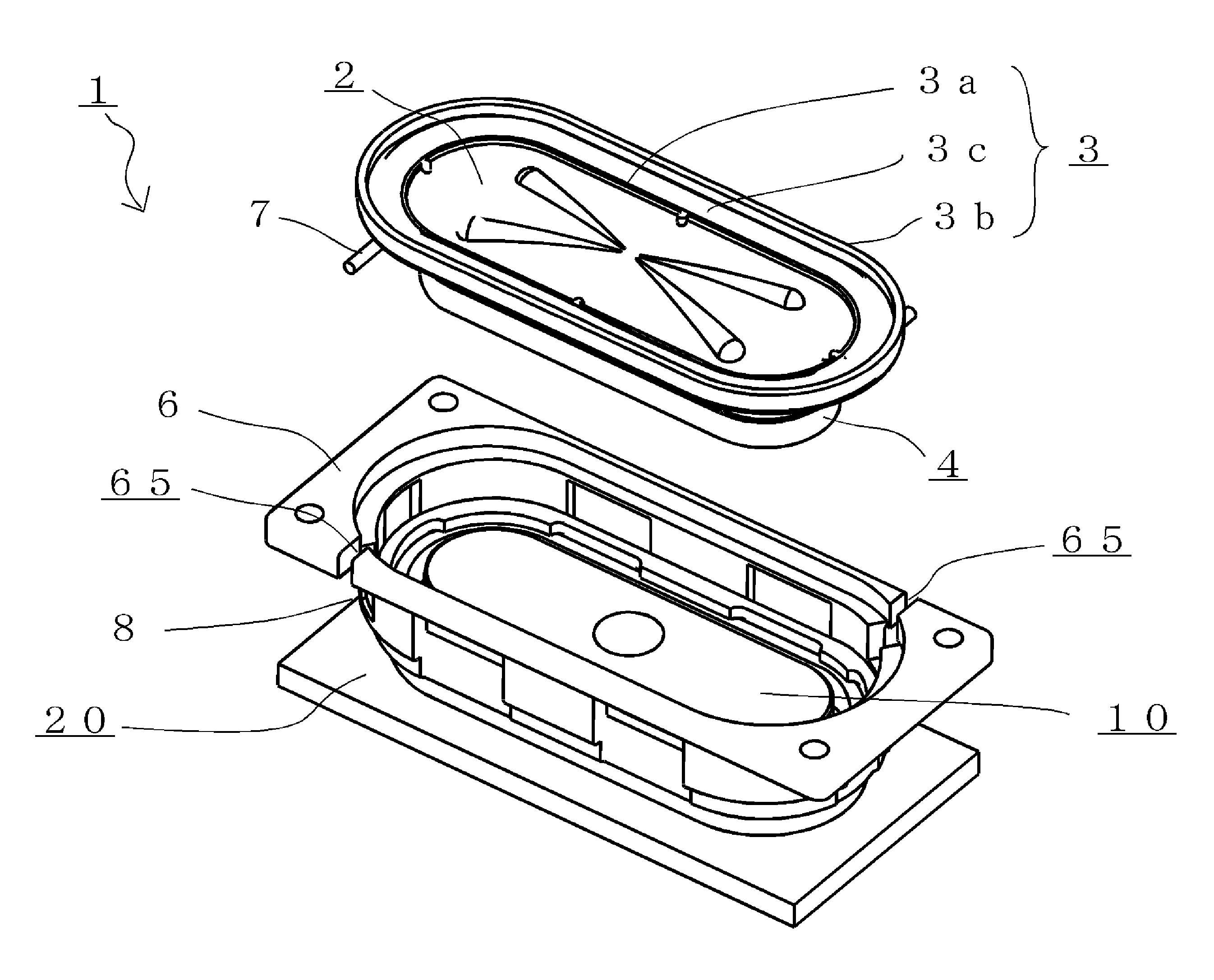
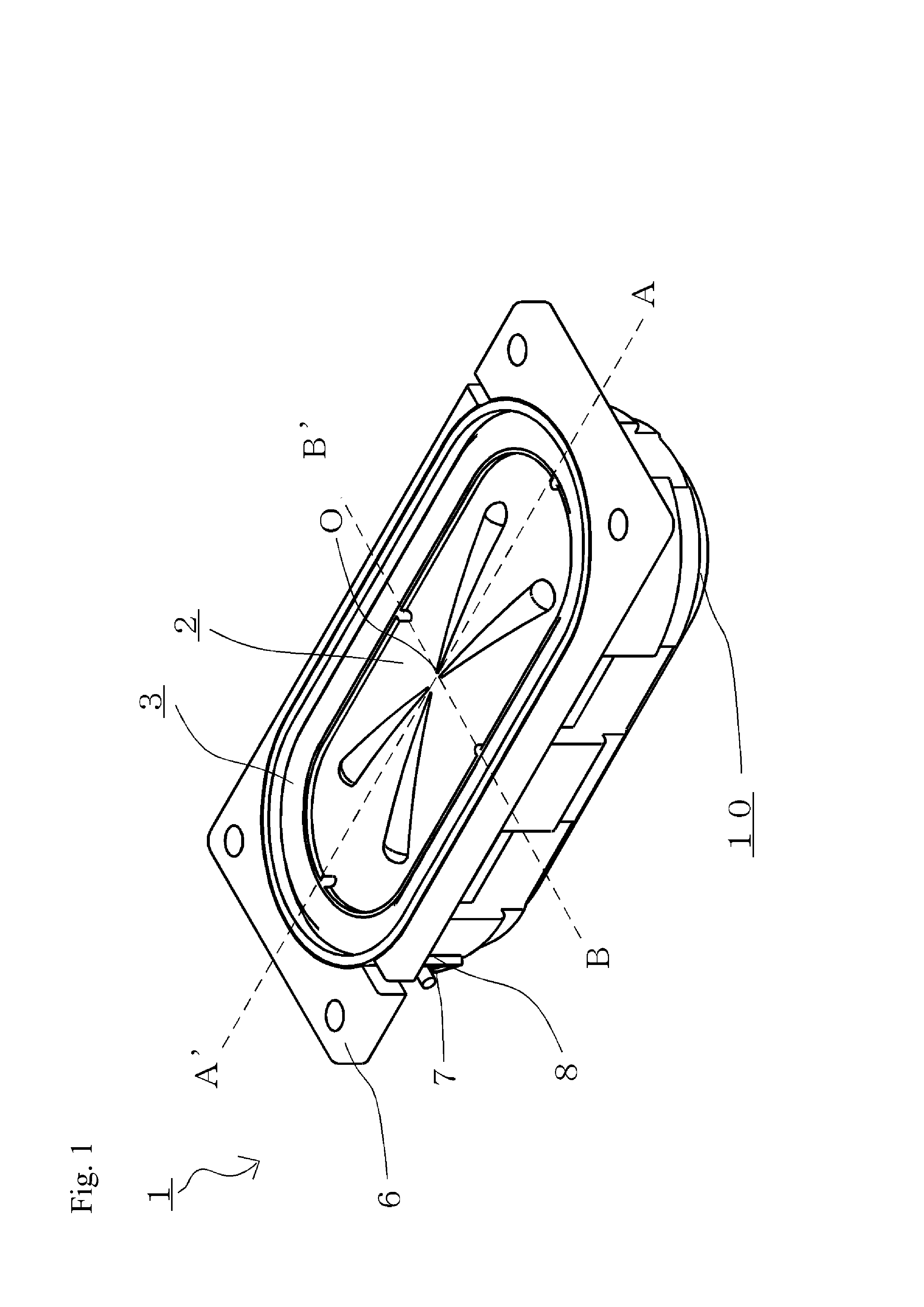
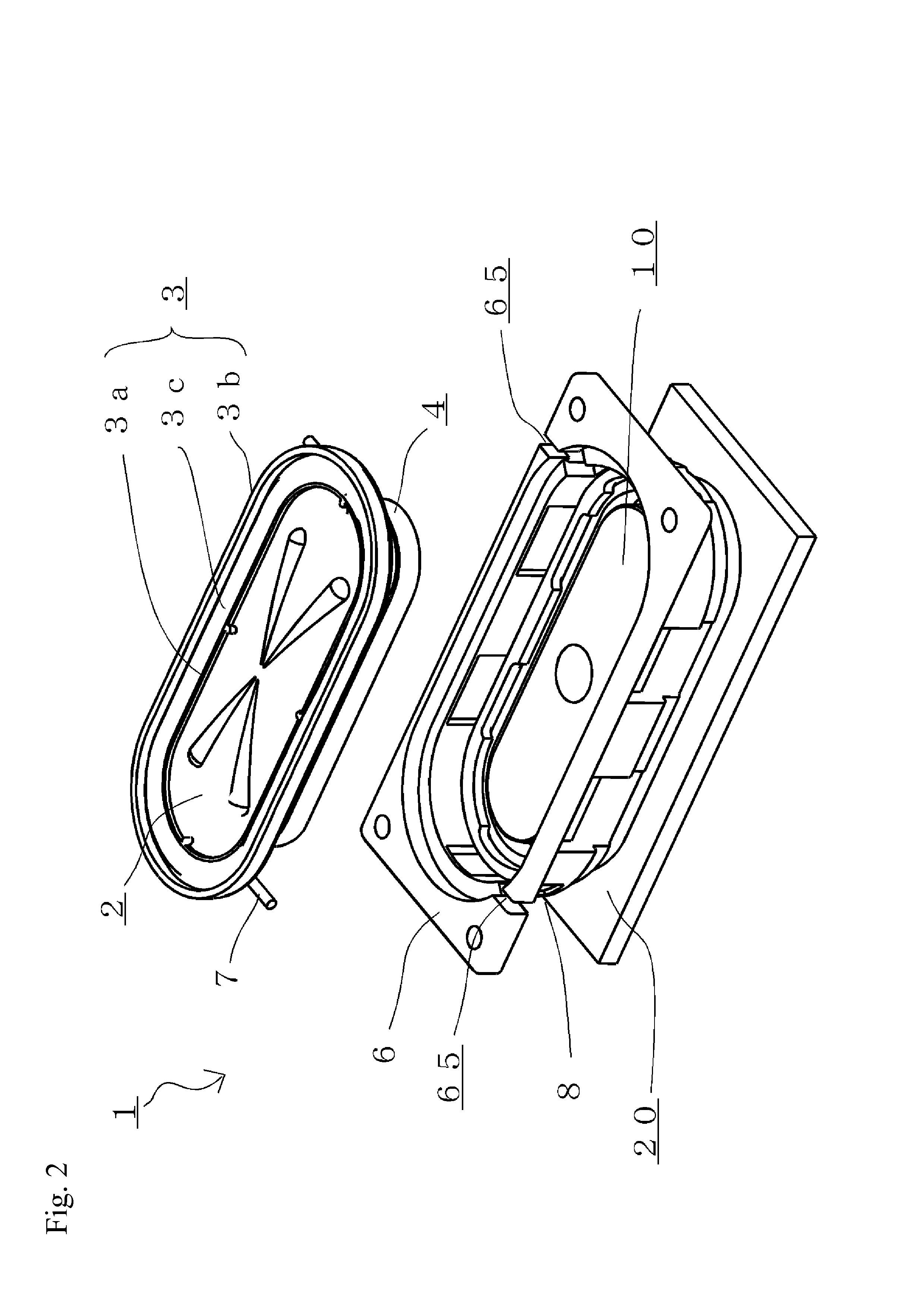
[0031]FIG. 1 and FIG. 2 are diagrams describing preferred embodiments of the present invention. Specifically, FIG. 1 is a perspective view illustrating the electrodynamic speaker 1. Further, FIG. 2 is a development diagram describing a structure of the electrodynamic speaker 1, and a perspective view where some parts unnecessary for the description are eliminated. The electrodynamic speaker 1 includes a vibration system including a track-shaped diaphragm 2, an edge 3 and a voice coil 4, a frame 6, and a magnetic circuit 10. The electrodynamic speaker 1 is manufactured by using an assembly jig 20. FIGS. 3A to 3C are diagrams describing the frame 6 of the electrodynamic speaker 1. FIG. 3A is a plan view, FIG. 3B and FIG. 3C are side views.

[0032]The electrodynamic spe...


PUM

PropertyMeasurementUnit
Magnetismaaaaaaaaaa

Abstract

An electrodynamic speaker in which the number of steps of forming a tinsel wire to be connected to a voice coil and connecting the tinsel wire to a terminal can be reduced is provided.
A frame of the electrodynamic speaker includes an edge mounting section, a magnetic circuit mounting section, a coupling section for coupling the edge mounting section and the magnetic circuit mounting section so as to define a plurality of window sections, a terminal fixing section for fixing a terminal, and at least one void for dividing the edge mounting section having an approximately annular shape, the void being communicatively connected to the window sections of the coupling section. A middle portion of the tinsel wire passes through the void or the window sections communicatively connected to the void, and the other end of the tinsel wire is connected and fixed to the terminal.

Description

BACKGROUND OF THE INVENTION[0001]1. Field of the Invention[0002]The present invention relates to a small electrodynamic speaker having excellent audio reproducing performance and including a frame and a magnetic circuit, the electrodynamic speaker in which the number of steps of forming the tinsel wire to be connected to a voice coil and connecting the tinsel wire to a terminal can be reduced, and relates to a method for manufacturing the electrodynamic speaker.[0003]2. Description of the Related Art[0004]In audio equipment such as displays to which speakers for reproducing audio are mounted, it is demanded that spaces required for mounting of speakers are made small. In particularly small or elongated (rectangular, oval (including an oblong shape and a track shape) electrodynamic speakers, since a space on a speaker diaphragm rear surface where a tinsel wire (or lead wire) for supplying an audio signal current to a voice coil is arranged is narrow, there is a problem that the tinse...

Claims


Application Information

Patent Timeline
IPC IPC(8): H04R3/00H04R31/00
CPCH04R3/00H04R31/00Y10T29/49005H04R1/1008H04R2499/15H04R1/06
Inventor FUJITANI, TAKESHI
Owner ONKYO KK
Why Eureka
Try Eureka