Method of using external fluid for cooling high temperature components of gas turbine for a process power plant

a technology of gas turbine and high temperature components, which is applied in the direction of engine components, machines/engines, mechanical apparatus, etc., can solve the problems of reducing the efficiency of the turbine's brayton cycle, reducing work, and reducing efficiency, so as to increase the net output and efficiency of the igcc system

Inactive Publication Date: 2013-07-25
GENERAL ELECTRIC CO
View PDF0 Cites 7 Cited by
  • Summary
  • Abstract
  • Description
  • Claims
  • Application Information

AI Technical Summary

Benefits of technology

[0010]It has been found that if a nitrogen fluid cooling arrangement is used to cool at least the first stage of gas turbine nozzles (S1N), and then if the nitrogen is dumped in the compressor discharge casing, the nitrogen cooling arrangement provides a 5% increase in IGCC net output and a 0.48 absolute pts improvement in IGCC net efficiency over the baseline scenario that is practiced in the current state of the art. This is achieved because combustor firing temperature is increased and closed loop heat is integrated in the gas turbine cycle.

Problems solved by technology

Open loop air cooling of stationary and rotating components of a gas turbine of an integrated gasification combined cycle (IGCC) Power Plant using air extracted from the compressor reduces the efficiency of the turbine's Brayton cycle, i.e., the thermodynamic cycle describing the operation of the gas turbine.
The reduction in efficiency occurs because of (a) a reduction in firing temperature due to non-chargeable flow diluting the combustor exit temperature, (b) a reduction in work because of the bypassing of compressed air at upstream stages of the turbine, and (c) a reduction in work potential (availability loss) because of the dilution effects of the coolant stream mixing in the main gas path and the associated loss of aerodynamic efficiency.

Method used


Image

  • Method of using external fluid for cooling high temperature components of gas turbine for a process power plant
  • Method of using external fluid for cooling high temperature components of gas turbine for a process power plant
  • Method of using external fluid for cooling high temperature components of gas turbine for a process power plant

Examples


Embodiment Construction

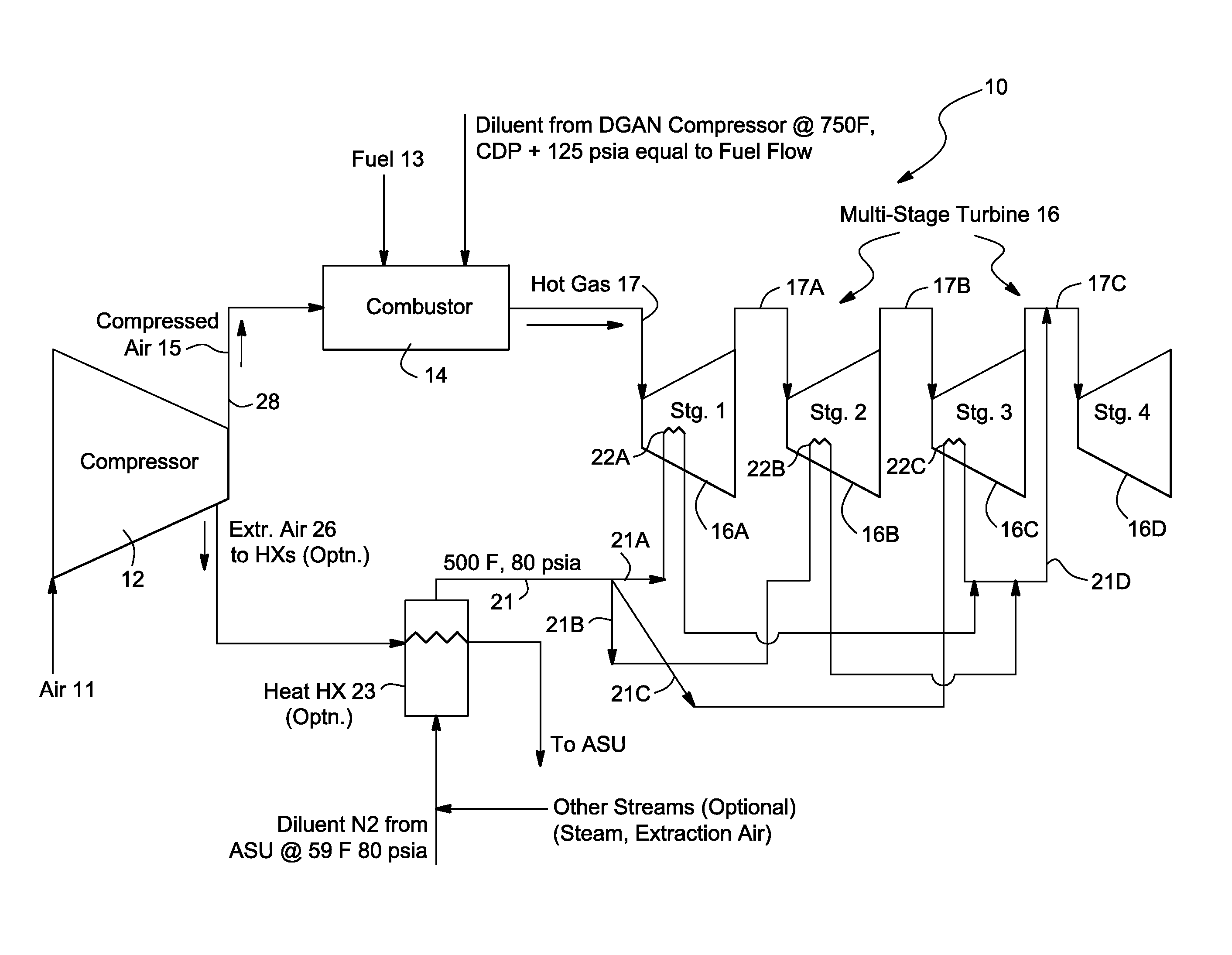
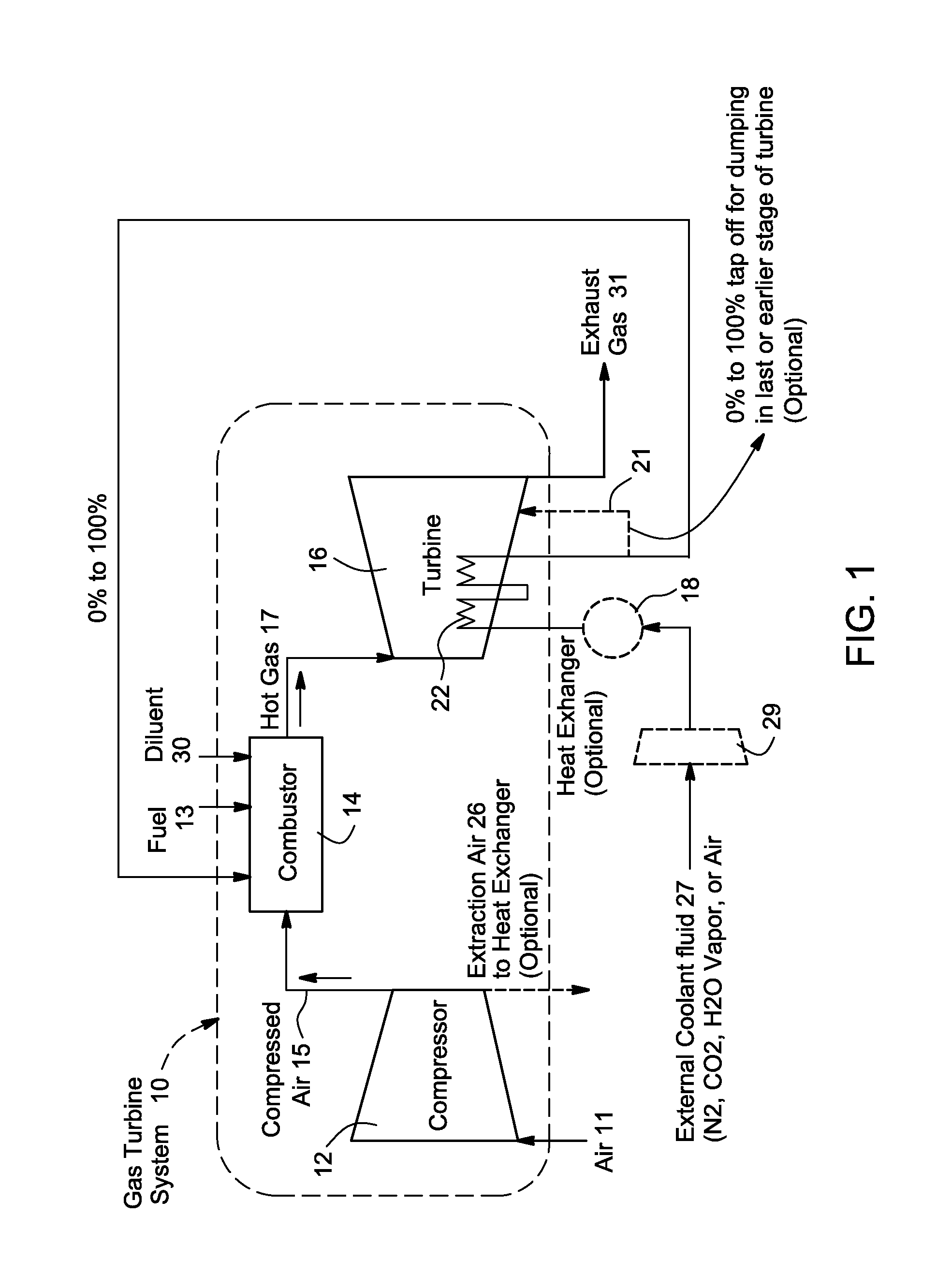
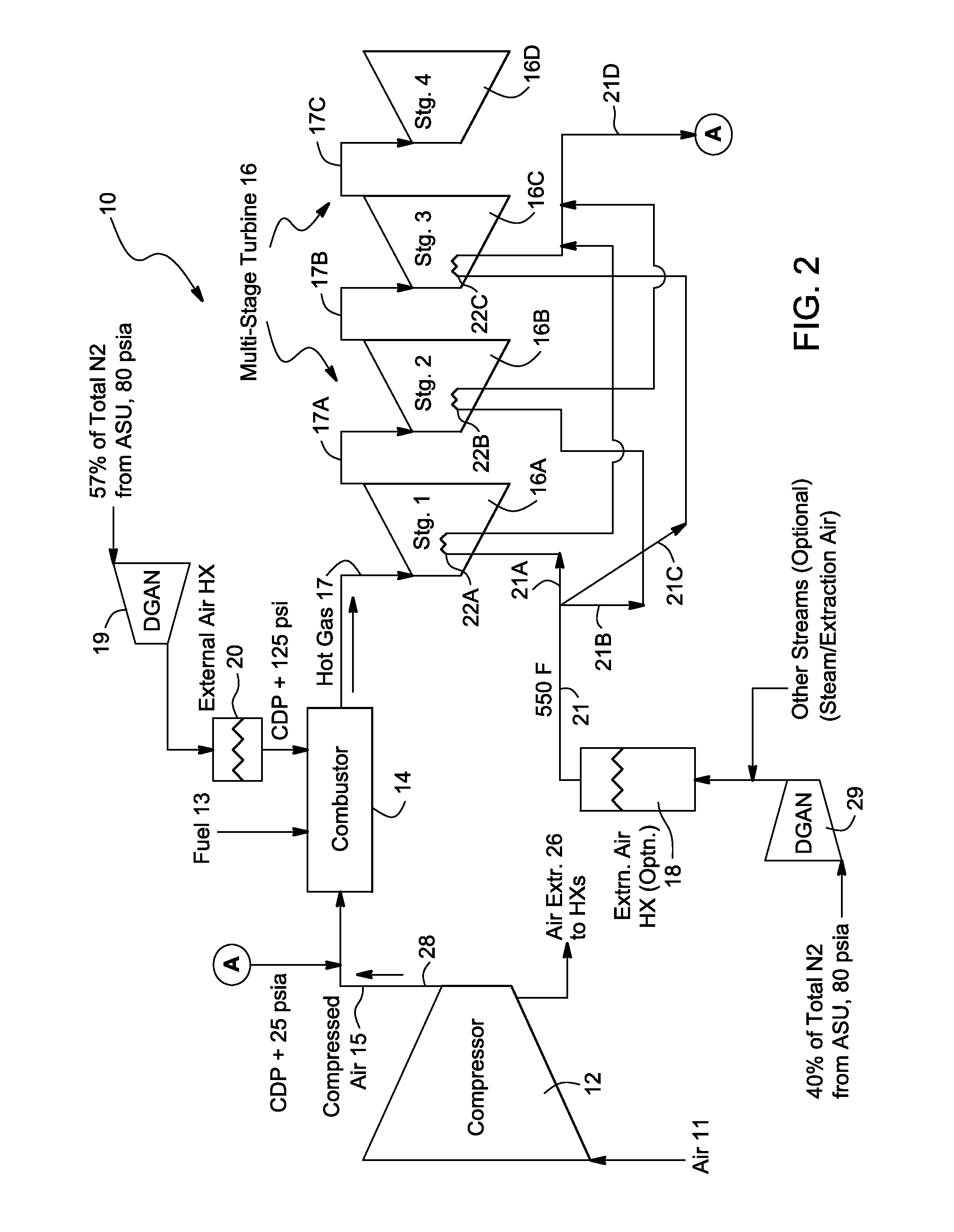
[0015]The present invention uses a fluid external to a gas turbine in a closed loop cooling arrangement to provide cooling of stationary and / or rotating hot gas path components of the gas turbine. The external fluid can be nitrogen gas, carbon dioxide, steam or air. Preferably, the external fluid is nitrogen which is obtained from an air separation unit (ASU) column, and then introduced into the closed loop to cool the hot gas path components of a gas turbine.

[0016]After cooling the turbine components, the heat removed using the external fluid flow is either dumped in the Compressor Discharge Casing (CDC) or dumped in the one of the stages of a multi-stage turbine. Preferably, the heated external fluid is dumped in the combustor / CDC, where the heat can be used at the best point of the turbine Brayton cycle. Alternatively, the heated external fluid can be dumped in an appropriate downstream turbine stage when the pressure of the heated fluid is not enough for the fluid to make it to ...


PUM


Abstract

An external fluid in a closed loop is used to cool hot gas path components of gas turbine. After cooling the turbine components, the heated external fluid is dumped either in the compressor discharge casing or in the one of the turbine's stages. Where the external fluid is nitrogen to be dumped in the turbine compressor's discharge casing, the nitrogen is compressed using diluent nitrogen compressors. Alternatively, where the external fluid is nitrogen to be dumped in one of the stages of the turbine, the nitrogen is not compressed at all. The turbine blade heat exchangers in the turbine stages through which the nitrogen passes can be connected in parallel or in series for cooling the hot gas path components in the turbine stages. The nitrogen can optionally be mixed with air or steam or not mixed at all.

Description

[0001]The present invention relates to turbines, and more particularly, to an arrangement using a fluid external to a gas turbine for a process power plant to cool high temperature components of the gas turbine.BACKGROUND OF THE INVENTION[0002]Open loop air cooling of stationary and rotating components of a gas turbine of an integrated gasification combined cycle (IGCC) Power Plant using air extracted from the compressor reduces the efficiency of the turbine's Brayton cycle, i.e., the thermodynamic cycle describing the operation of the gas turbine. The reduction in efficiency occurs because of (a) a reduction in firing temperature due to non-chargeable flow diluting the combustor exit temperature, (b) a reduction in work because of the bypassing of compressed air at upstream stages of the turbine, and (c) a reduction in work potential (availability loss) because of the dilution effects of the coolant stream mixing in the main gas path and the associated loss of aerodynamic efficienc...

Claims


Application Information

Patent Timeline
Patent Type & Authority Applications(United States)
IPC IPC(8): F02C7/12F02C6/08
CPCF02C7/18Y02E20/18Y02E20/16
Inventor MUNDRA, KAMLESHANAND, ASHOK KUMARMUTHAIAH, VEERAPPAN
Owner GENERAL ELECTRIC CO
Why Eureka
Try Eureka