A fuel cell thermal management system and control method with adjustable heat exchange

A thermal management system and fuel cell technology, applied in the direction of fuel cell heat exchange, fuel cell, fuel cell additives, etc., can solve the problems of unstable operation of the fuel cell system, lowering the temperature of the coolant, unable to utilize heat, etc. The effect of starting preheating power consumption, reducing working pressure and avoiding heat dissipation

Active Publication Date: 2022-08-05
金华氢途科技有限公司
View PDF7 Cites 0 Cited by
  • Summary
  • Abstract
  • Description
  • Claims
  • Application Information

AI Technical Summary

Problems solved by technology

[0003] The existing technical scheme, the basic scheme is two temperature sampling points (T1 / T2), a water pump, a radiator, a heater, a water tank, and a three-way valve, wherein the temperature sampling point provides a thermal management control system State input, the water pump is used to adjust the flow of coolant, the heater is used to quickly increase the temperature of the heat management coolant, the radiator lowers the temperature of the coolant, the three-way valve adjusts the flow of the heater branch, and the water tank stores the coolant; however, the existing technology There are the following deficiencies: 1. The heat generated by the fuel cell system is dissipated to the external environment through the thermal management system, and the heat cannot be effectively used; If a lot of waste heat is not produced, the cooling fluid of the thermal management system will generate a certain amount of heat dissipation when it flows through the radiator. 3. When the heat exchange method is used, the heat management system is only structurally exchanging heat with the external heat demand system through the heat exchanger, but it cannot be controlled or known. The heat demand of the external heat demand system may cause a large amount of heat to be exchanged through the heat exchange system due to the low temperature of the external heat demand system itself, resulting in a rapid drop in the temperature of the thermal management system, resulting in unstable operation of the fuel cell system

Method used


Image

  • A fuel cell thermal management system and control method with adjustable heat exchange
  • A fuel cell thermal management system and control method with adjustable heat exchange

Examples


Embodiment Construction

[0040] In order to make the objectives, technical solutions and advantages of the present invention clearer, the present invention will be further described in detail below through the accompanying drawings and embodiments. However, it should be understood that the specific embodiments described herein are only used to explain the present invention, and not to limit the scope of the present invention. Also, in the following description, descriptions of well-known structures and techniques are omitted to avoid unnecessarily obscuring the concepts of the present invention.

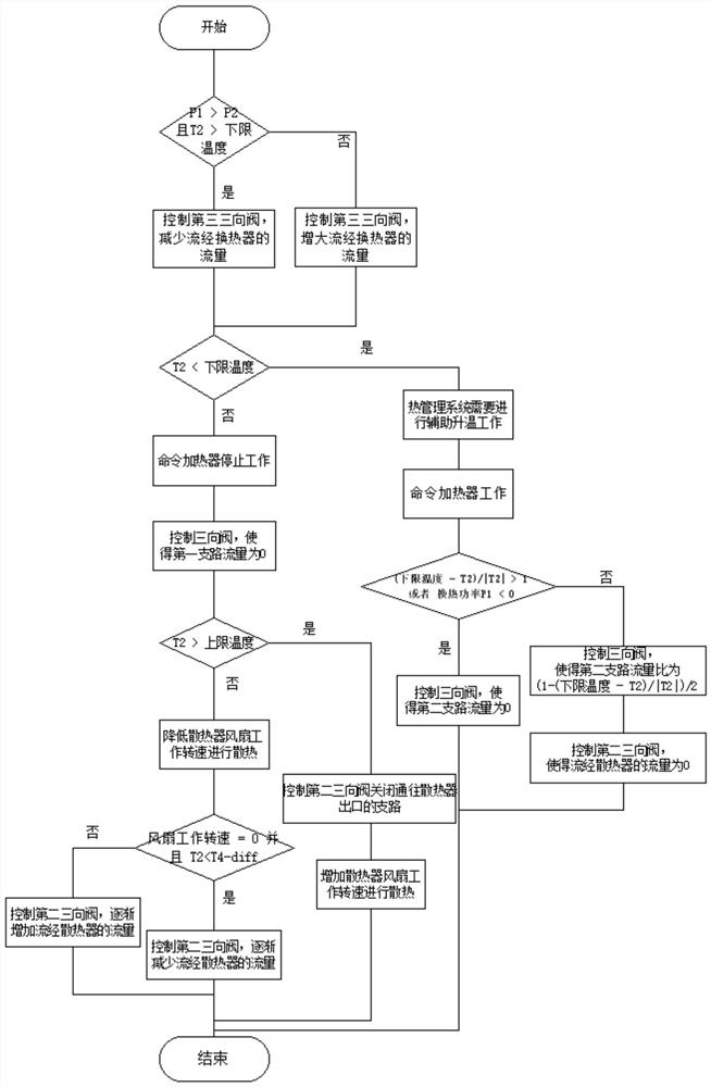
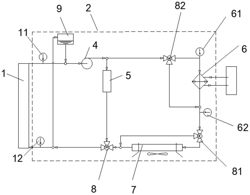
[0041] see figure 1 , the present application is a control method of a fuel cell thermal management system with adjustable heat exchange, comprising the following steps:

[0042] S1. The control unit receives the preset upper limit temperature and lower limit temperature, and obtains the temperature value T1 at the outlet of the cooling liquid pipeline, the temperature value T2 at the inlet of the cooling l...


PUM


Abstract

The present invention provides a fuel cell thermal management system with heat energy recovery and a control method. The heat generated by the fuel cell system is used to provide heat for other components requiring heat by exchanging heat between a heat exchanger and a heat storage system. Effective use of heat; adding a third three-way valve, the thermal management system can actively adjust the heat exchange of the heat exchanger in real time, ensuring the stability of its own temperature, and is designed to judge when the temperature value T2 is greater than or equal to the lower limit temperature. The solution of whether the heat exchange power P1 of the heat exchanger is greater than the heat generation power P2 of the fuel cell module ensures that the heat exchange of the heat exchanger will not be greater than the waste heat generated by the fuel cell system, and also ensures that the heat management can quickly enter the fuel The lower limit temperature required by the battery system enables the fuel cell system to enter a suitable operating temperature more quickly.

Description

technical field [0001] The invention relates to the technical field of fuel cell systems, in particular to a fuel cell thermal management system and a control method with adjustable heat exchange. Background technique [0002] A fuel cell system is a device that converts fuel (reducing agent) and oxygen (oxidizing agent) into electrical energy by electrochemical means. The basic principle of hydrogen fuel cell is 2H2+O2→2H2O+electrical energy+thermal energy. Under the continuous operation of the fuel cell, its thermal energy will continue to accumulate, causing the temperature of the entire system to rise. At this time, the thermal management system is required to thermally manage the fuel cell system to ensure that the fuel cell can work at a suitable temperature. [0003] The existing technical solution, the basic solution is two temperature sampling points (T1 / T2), a water pump, a radiator, a heater, a water tank, and a three-way valve, wherein the temperature sampling po...

Claims


Application Information

Patent Timeline
Patent Type & Authority Patents(China)
IPC IPC(8): H01M8/04007H01M8/04225H01M8/04302H01M8/0432
CPCH01M8/04328H01M8/04302H01M8/04225H01M8/04067Y02E60/50
Inventor 周鸿波郭志阳陈建山刘志洋胡钱坤
Owner 金华氢途科技有限公司
Why Eureka
Try Eureka