Capacitor discharging circuit and converter

Active Publication Date: 2013-07-25
DELTA ELECTRONICS SHANGHAI CO LTD
View PDF3 Cites 26 Cited by
  • Summary
  • Abstract
  • Description
  • Claims
  • Application Information

AI Technical Summary

Benefits of technology

[0017]As can be seen from the technical solution stated above, the capacitor between the live line and the null line of the AC power input terminal connected with the converter is discharged by the energy transfer unit, not by a discharging resistor, which is one of the features of the present application. When AC power is introduced, the conversion module performs power conversion as its original design; when AC power is disconnected, the control unit controls the energy transfer unit to transfer the energy stored in the capacitor between the live line and the null line of the AC power input terminals connected with the converter to the energy storage component of the conversion module, so as to achieve rapid discharge for the capacitor. In this way, the tec

Problems solved by technology

Specifically positioned, X-capacitor will be charged upon the introduction of AC power, and will store energy in power plug when AC power is disconnected, which is likely to induce current leakage or make the enclosure charged to endanger user safety.
However, the discharging resistor 3 connected in parallel in the circuit will consume energy all along and induce energy consumption, especially, the energy

Method used


Image

  • Capacitor discharging circuit and converter
  • Capacitor discharging circuit and converter
  • Capacitor discharging circuit and converter

Examples


Embodiment Construction

[0043]Some exemplary embodiments explaining the features and advantages of the present invention will be stated in detail in the following description. It is to be understood that different embodiments of the present invention have a variety of variations, which will fall within the scope of the present invention, and the description and figure showing are essentially used to explain the present invention, but not to limit the present invention.

[0044]The features and beneficial effects mentioned above, as well as other features and effects will be described in detail with embodiments of the capacitor discharging device of the present invention and the converter comprising the capacitor discharging device considered in conjunction with the attached FIGS. 2-23.

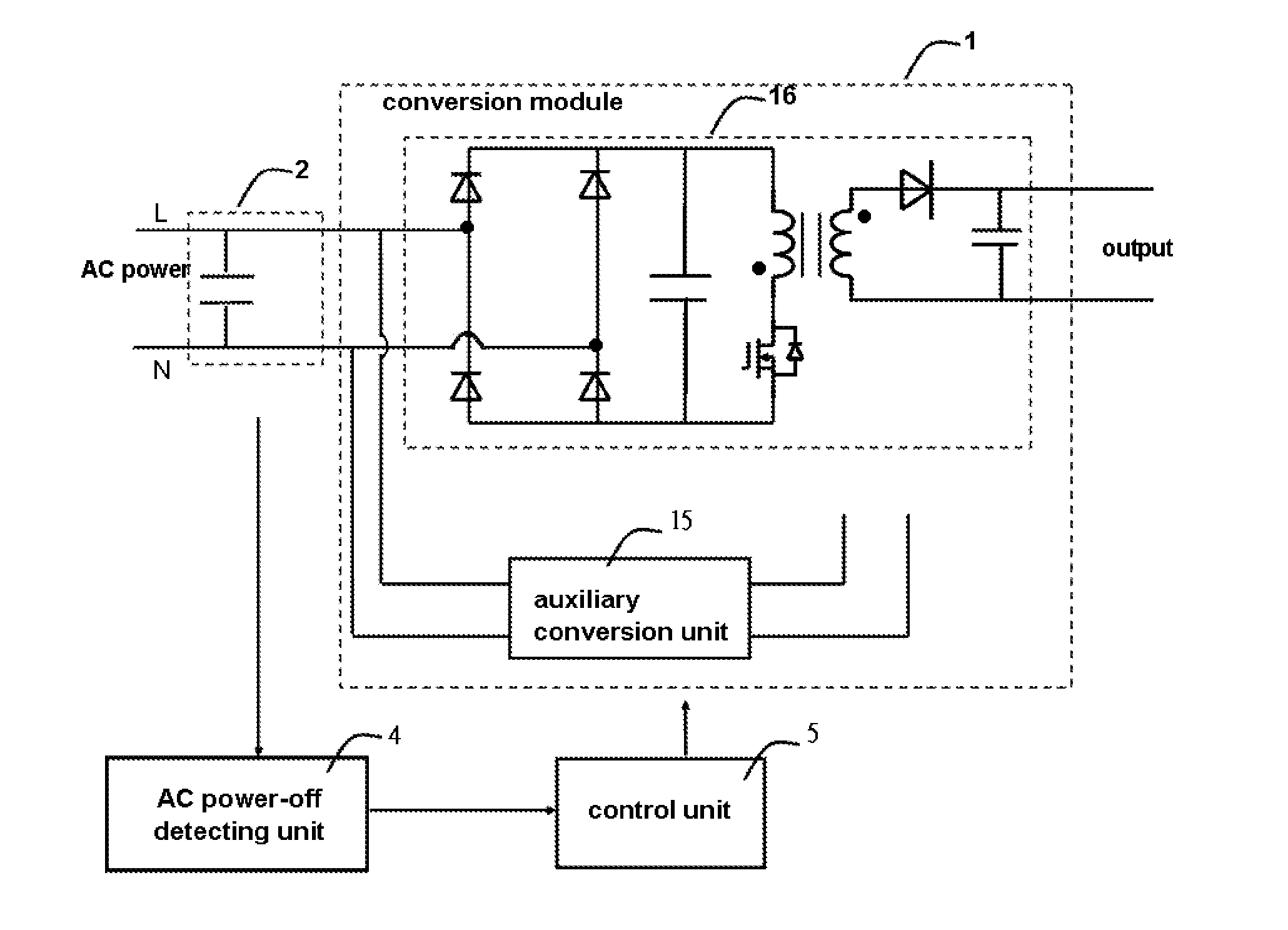
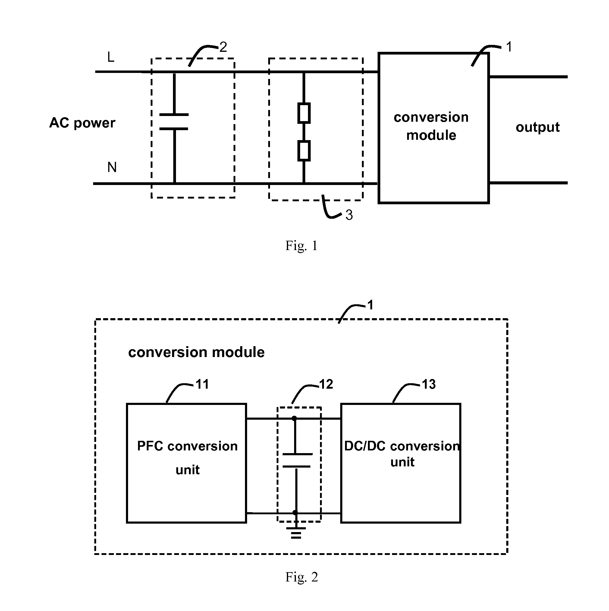
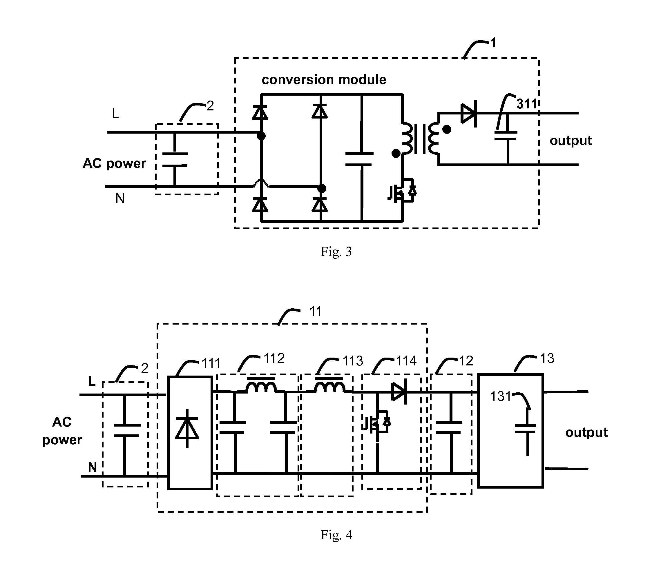
[0045]For an AC-AC and / or an AC-DC converter, a filter structure is usually coupled between the AC power input terminals. According to the requirement of “safety of information technology equipment”, the capacitor of the filter ...


PUM


Abstract

A capacitor discharging circuit and a converter are disclosed. The converter comprises: a capacitor connected between the live line and null line of an AC power input terminals, a conversion module coupled to the capacitor and comprising an energy storage component at least, an energy transfer unit coupled with the energy storage component and the capacitor, an AC power-off detecting unit and a control unit; wherein the energy transfer unit comprises a switch device; when AC power is disconnected, the AC power-off signal triggers the control unit to output a switch driving signal, controlling the operation of the energy transfer unit to transfer the energy stored in the capacitor to the energy storage component to discharge the capacitor.

Description

CROSS REFERENCE TO RELATED APPLICATIONS[0001]This application claims priority under 35 U.S.C. §119(a) to the Chinese patent application No. 201210019920.9, filed on Jan. 20, 2012, which is incorporated herein by reference in its entirety.FIELD OF THE INVENTION[0002]The present invention generally relates to power electronic technology, and more particularly to a capacitor discharging circuit and a converter comprising the capacitor discharging circuit.BACKGROUND OF THE INVENTION[0003]Under normal circumstance, in order to meet the requirement of electromagnetic compatibility, a filter configuration comprising a capacitor is connected between AC power and the electronic devices. In compliance with the “safety of information technology equipment” standard, the capacitor is a safety capacitor which comprises X-capacitors and Y-capacitors. X-capacitor is connected between L line (Live line) and N line (Null line) of the input terminals of AC power.[0004]Specifically positioned, X-capaci...

Claims


Application Information

Patent Timeline
IPC IPC(8): H02M3/335
CPCH02H3/14H02M1/4225Y02B70/126H02M2001/322H02M1/4258Y02B70/10Y02P80/10H02M1/322H02M1/0085
Inventor JIN, HONGYUANWANG, BAOCHENGAN, HONGJIANYING, JIANPING
Owner DELTA ELECTRONICS SHANGHAI CO LTD
Why Eureka
Try Eureka