Network system and communication traffic controlling method

a network system and communication traffic technology, applied in the field of network systems, can solve the problems of network erroneously setting the routing and unintentional formation of loops

Inactive Publication Date: 2013-07-25
NEC CORP
View PDF2 Cites 50 Cited by
  • Summary
  • Abstract
  • Description
  • Claims
  • Application Information

AI Technical Summary

Benefits of technology

[0022]An object of the present invention is to provide a network system in which a packet of a cause is dropped in a flow unit, when a t

Problems solved by technology

In the routing environment with a high degree of freedom like the open flow (OpenFlow) network, there is a possibility that a person who builds a network

Method used


Image

  • Network system and communication traffic controlling method
  • Network system and communication traffic controlling method
  • Network system and communication traffic controlling method

Examples


implementation example

(Implementation Example)

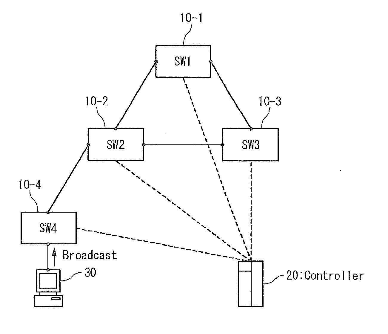
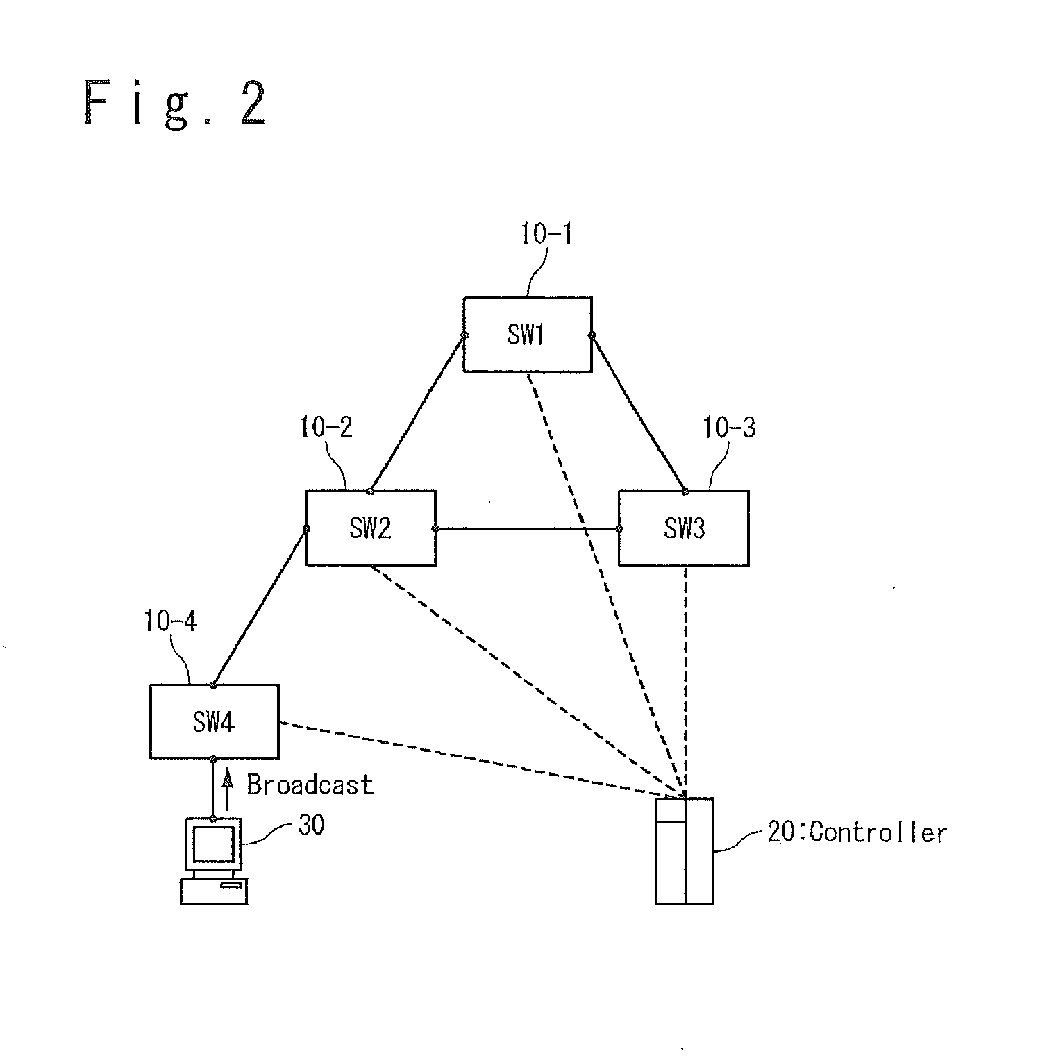
[0056]A network configuration in which a loop is configured by the switch 10-1 (SW1), the switch 10-2 (SW2) and the switch 10-3 (SW3) will be described as an example as shown in FIG. 3.

[0057]As shown in FIG. 3, in this network configuration, the terminal 30 is connected with the switch 10-4 (SW4) and the switch 10-4 (SW4) is connected with the switch 10-2 (SW2).

[0058]Also, in this network configuration, the controller 20 is connected to each of the switches 10 (10-i, i=1-n) by a secure channel to control each switch 10.

[0059]In this condition, the terminal 30 transmits the ARP packet which causes the traffic storm.

[0060](Basic Operation)

[0061]Referring to FIGS. 4A and 4B, an operation of each unit of the network system according to the present invention will be described.

[0062](1) Step S101

[0063]The controller 20 acquires the statistic data for every port of the switch 10 as each control target in a constant interval (regularly). For example, the controller 2...


PUM


Abstract

When a traffic storm has occurred in an open flow network, a frame of a cause is dropped in a flow unit without carrying out the indiscriminate drop of the frame and the down of the port. Specifically, a controller detects increase of the traffic in a short time from the statistic data regularly acquired from each of the switches under the control of it. The controller starts a storm detection mode upon the detection. In the storm detection mode, packets are extracted randomly from the switch for a predetermined time period, as a sample packet. The controller determines which of a broadcast storm, a multicast storm and a unicast storms has occurred, based on the sample packets. The controller determines that the traffic storm has occurred, when any of them has occurred.

Description

TECHNICAL FIELD[0001]The present invention relates to a network system, and more particularly a network system which controls a traffic storm caused in an open flow (OpenFlow) compatible device.BACKGROUND ART[0002]As one of routing control techniques in the network communication, a routing control technique which uses the open flow (OpenFlow) technique as a control protocol of a transmitter is studied. The details of the open flow technique will be described in Non-Patent Literatures 1 and 2. A network in which the routing control is carried out based on the open flow technique is called an open flow network.[0003]In the open flow network, a controller such as an OFC (OpenFlow controller) controls the behavior of each of switches by manipulating flow tables of the switches such as an OFS (OpenFlow switch). The controller and the switch are connected by a secure channel which is used for the controller to control the switch by using a control message conformed to the open flow protoc...

Claims


Application Information

Patent Timeline
IPC IPC(8): H04L12/56H04L45/02H04L45/18H04L45/28H04L45/42H04L47/22H04L47/32
CPCH04L49/555H04L49/557H04L47/323H04L45/70H04L45/38H04L63/0227H04L47/32H04L63/1441H04L45/64H04L12/28
Inventor SATO, SHIHOMI
Owner NEC CORP
Why Eureka
Try Eureka