Particle reducing method and film deposition method

a technology of film deposition and particle reduction, which is applied in the direction of chemical vapor deposition coating, coating, chemical apparatus and processes, etc., can solve the problems of particle peeled objects, and achieve the effect of reducing particles

Active Publication Date: 2013-07-25
TOKYO ELECTRON LTD
View PDF3 Cites 17 Cited by
  • Summary
  • Abstract
  • Description
  • Claims
  • Application Information

AI Technical Summary

Benefits of technology

[0012]The present invention is made in light of the above problems, and provides a particle reducing method capable of reducing particles caused by a susceptor on which a substrate is to be mounted.

Problems solved by technology

When forming a thin film on a wafer using such a film deposition apparatus, there is a problem that a deposited object is also formed inside the chamber to cause particles when the deposited object is peeled.

Method used


Image

  • Particle reducing method and film deposition method
  • Particle reducing method and film deposition method
  • Particle reducing method and film deposition method

Examples


Embodiment Construction

[0028]The invention will be described herein with reference to illustrative embodiments. Those skilled in the art will recognize that many alternative embodiments can be accomplished using the teachings of the present invention and that the invention is not limited to the embodiments illustrated for explanatory purposes.

[0029]It is to be noted that, in the explanation of the drawings, the same components are given the same reference numerals, and explanations are not repeated. Further, drawings are not intended to show relative ratios of a component or components.

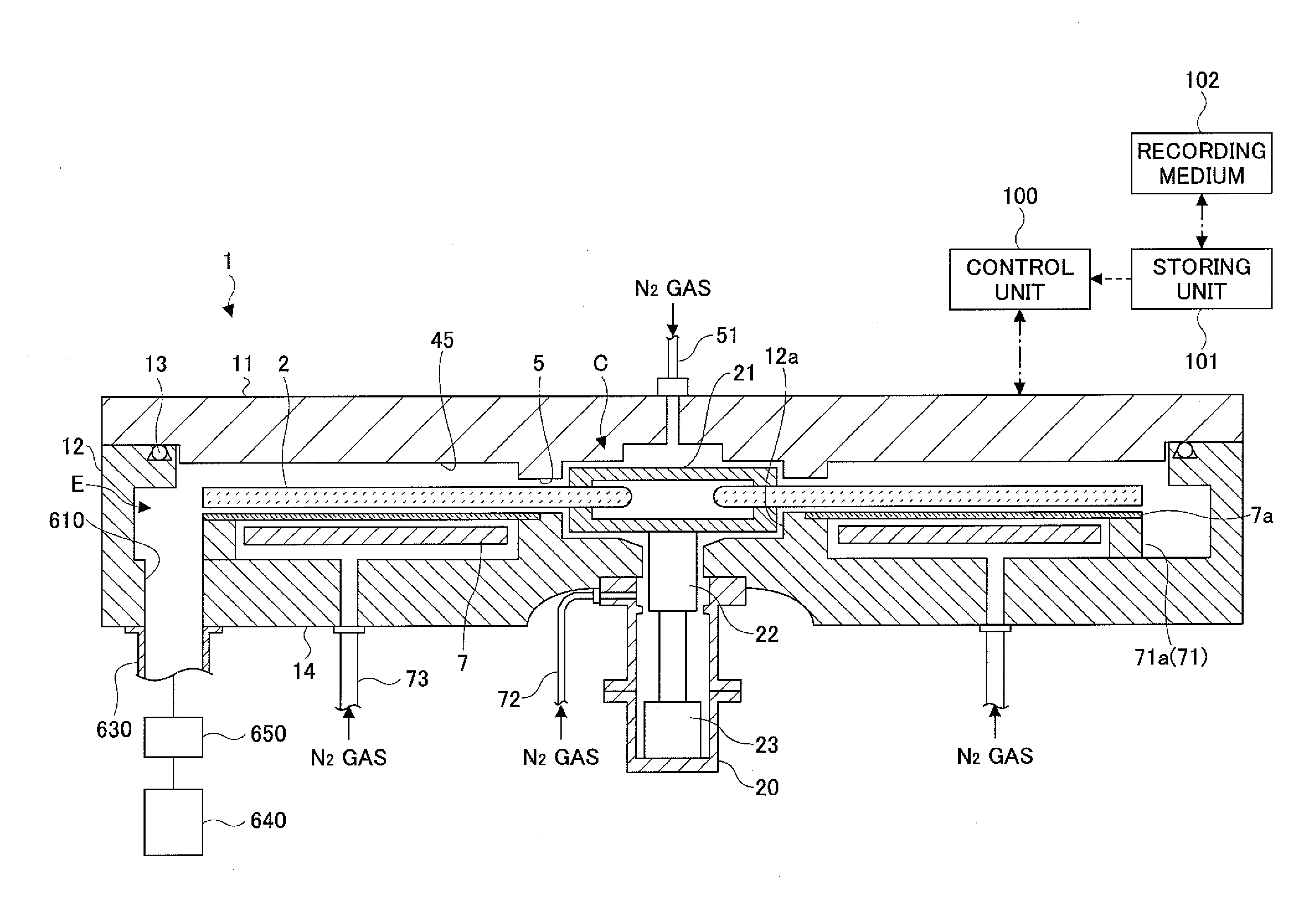
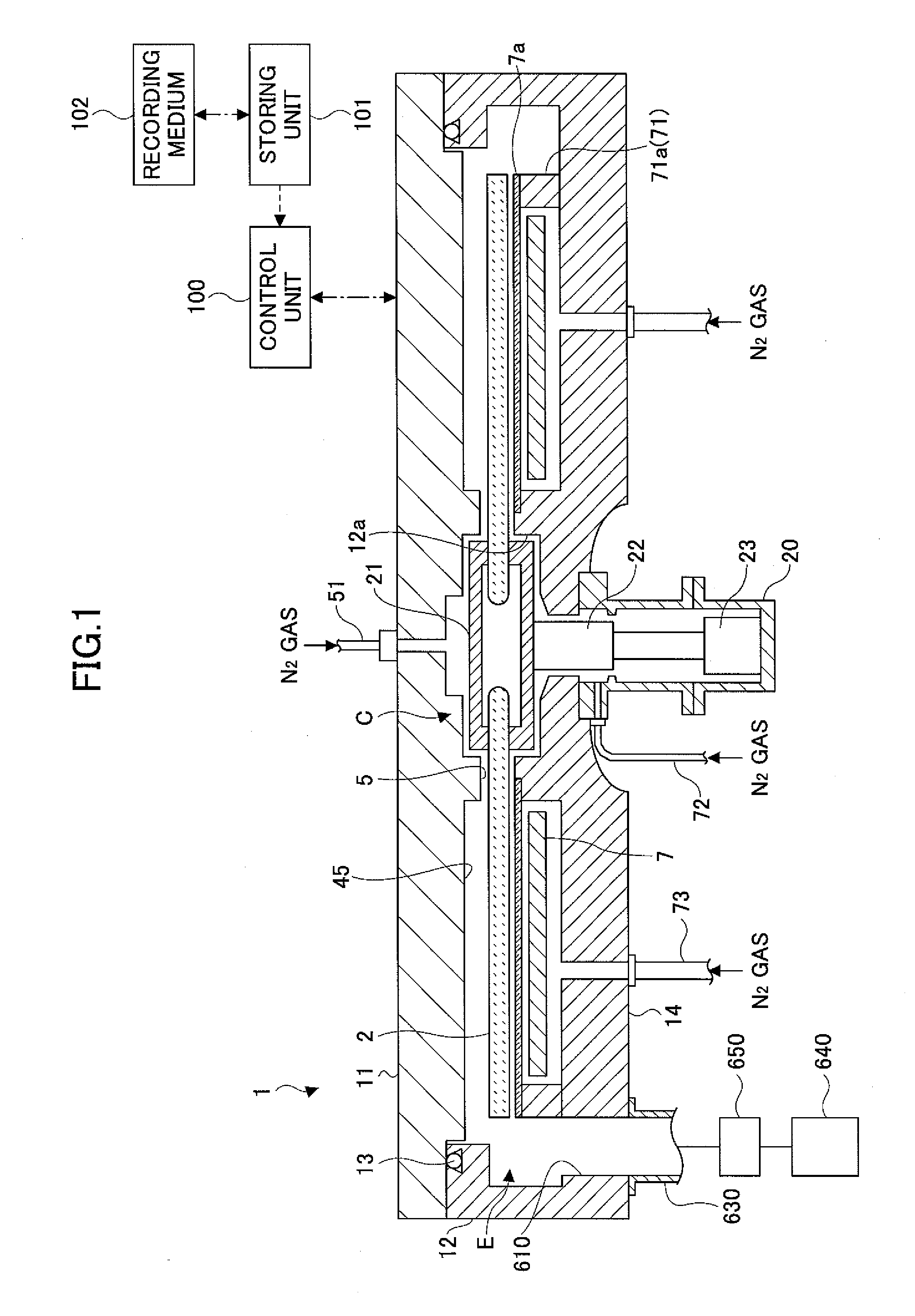
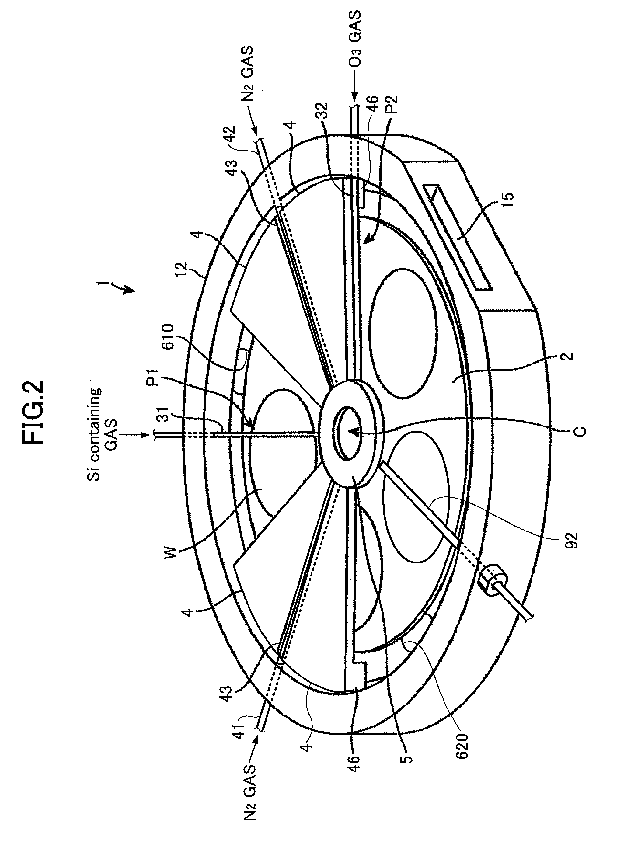
[0030]First, a mechanism in which particles are generated in a substrate processing apparatus (such as the above described ADL apparatus) is explained.

[0031]The present inventors have found that the particles may be generated by the following reason(s) after extensive research.

[0032]The susceptor included in the above described ALD apparatus may be manufactured by forming a concave portion on which a wafer can be mounted on...


PUM

PropertyMeasurementUnit
diameteraaaaaaaaaa
diameteraaaaaaaaaa
temperatureaaaaaaaaaa

Abstract

A particle reducing method includes a step of supplying a first gas to a vacuum chamber in which a susceptor, formed by an insulating object and the surface of which is provided with a substrate mounting portion, is rotatably provided; a step of generating plasma from the first gas by supplying high frequency waves to a plasma generating device provided for the vacuum chamber; and a step of exposing the substrate mounting portion, on which a substrate is not mounted, to the plasma while rotating the susceptor.

Description

CROSS-REFERENCE TO RELATED APPLICATION[0001]The present application is based on Japanese Priority Application No. 2012-010162 filed on Jan. 20, 2012, the entire contents of which are hereby incorporated herein by reference.BACKGROUND OF THE INVENTION[0002]1. Field of the Invention The present invention relates to a particle reducing method and a film deposition method.[0003]2. Description of the Related Art[0004]A film deposition method in which a thin film is formed on a semiconductor wafer (hereinafter, referred to as a “wafer”) is known as one of methods of manufacturing a semiconductor integrated circuit. A film deposition apparatus which is used for the film deposition method includes a sealable chamber, a susceptor provided in the chamber on which a wafer is to be mounted, a source gas supplying unit which supplies a source gas onto the wafer mounted on the susceptor, and an evacuation device which is connected to the chamber and evacuates the source gas.[0005]When forming a t...

Claims


Application Information

Patent Timeline
Patent Type & Authority Applications(United States)
IPC IPC(8): H01L21/02
CPCH01L21/0206H01J37/32733C23C16/4554C23C16/45551C23C16/4581H01J2237/20214H01J2237/201H01J2237/032H01J37/32825H01J2237/332H01J37/32715H01J37/32458C23C16/50C23C16/4584C23C16/4405H01L21/02H01L21/205
Inventor KATO, HITOSHIKIKUCHI, HIROYUKIKUMAGAI, TAKESHI
Owner TOKYO ELECTRON LTD
Why Eureka
Try Eureka