Method for manufacturing bonded magnet
a technology of bonded magnets and manufacturing methods, applied in the direction of magnetic bodies, inorganic material magnetism, magnetic materials, etc., can solve the problems of insufficient magnetization characteristics, difficulty in multi-pole magnetization, and difficulty in applying pulse current enough to magnetize magnetics, etc., to achieve low cost, reduce thermal demagnetization characteristics, and improve the effect of magnetic properties
Inactive Publication Date: 2013-08-01
MINEBEA CO LTD
View PDF1 Cites 7 Cited by
- Summary
- Abstract
- Description
- Claims
- Application Information
AI Technical Summary
Benefits of technology
The present invention provides a method for making a bonded magnet that has high magnetic characteristics and can be easily adjusted to have different levels of magneticization. This method is cost-effective. The technical effects of this invention are a decrease in Curie temperature and thermal demagnetization characteristics, which can be used to create the desired magnetic properties.
Problems solved by technology
Thus, a magnetization pitch (a magnetization distance between poles) becomes narrow, causing a difficulty in multi-pole magnetization.
Thus, the magnetization fixtures have problems of difficulty in applying pulse current enough to magnetize magnetics.
However, the magnetization methods of Japanese Patent No. 2940048 (Patent Literature 1) and Japanese Unexamined Patent Application Publication No. 6-140248 (Patent Literature 2) do not provide sufficient magnetization characteristics.
In addition, possibility of insulation breakdown cannot be avoided because electric current passes through a magnetic wire of a magnetization coil.
Since a magnetization fixture is subjected to high temperature, its component parts, especially mold resin, is deteriorated to shorten the life of the magnetization fixture.
However, since an adjustable range of magnetization characteristics depends on physical properties of magnetic particles, such a range typically becomes narrow and leads to difficulty in obtaining desired magnetization characteristics.
Method used
View moreImage
Smart ImageViewing Examples
Examples
example 1
[0037]A magnetic powder having an intrinsic coercive force of 716 kA / m (9 kOe) was prepared using a rare-earth iron boron bonded magnet 14 in which rare-earth elements were Nd and Pr.
example 2
[0038]A magnetic powder having an intrinsic coercive force of 796 kA / m (10 kOe) was prepared using a rare-earth iron boron bonded magnet 14 in which rare-earth elements were Nd and Pr.
Login to View More PUM
 Abstract
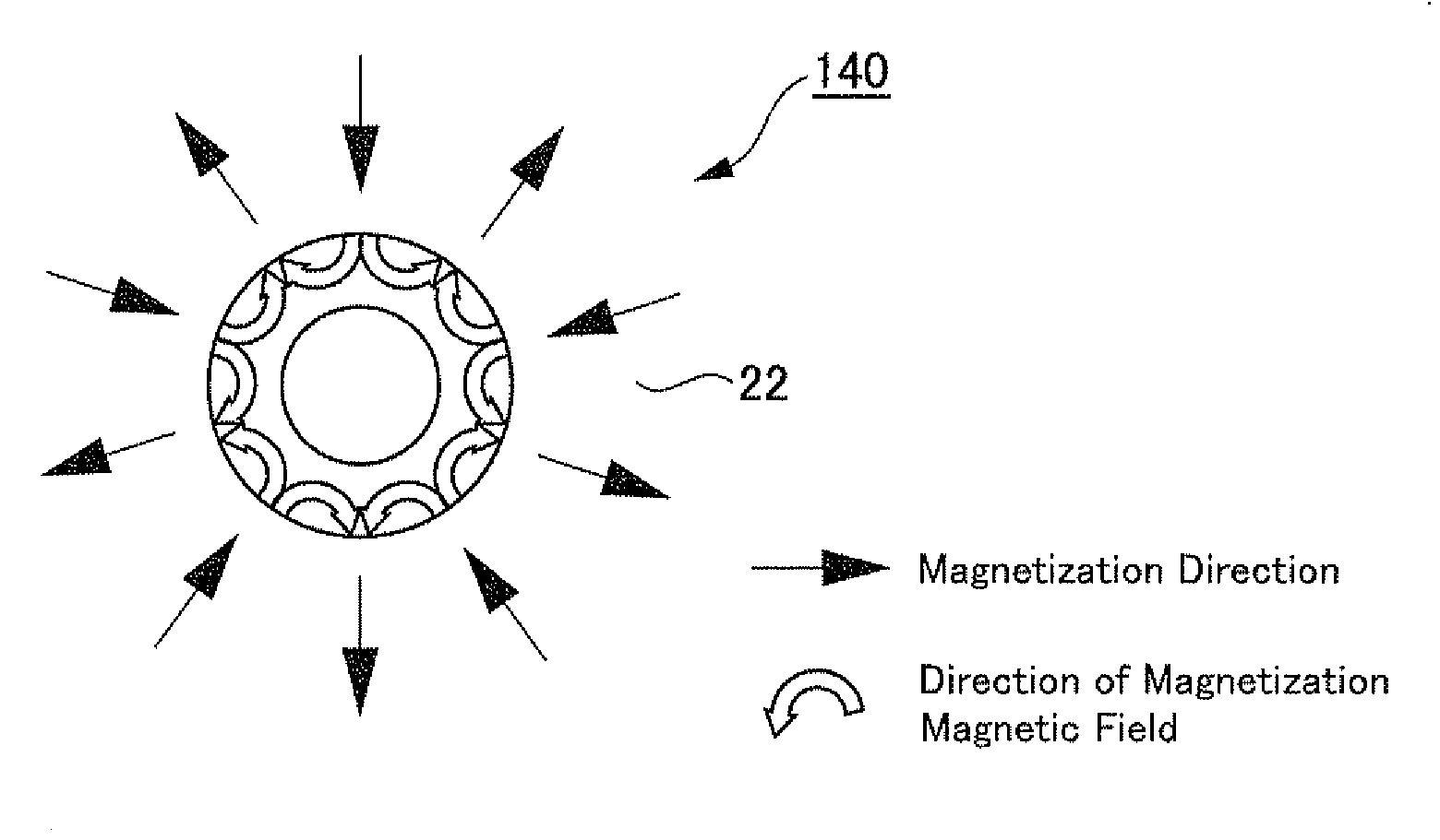
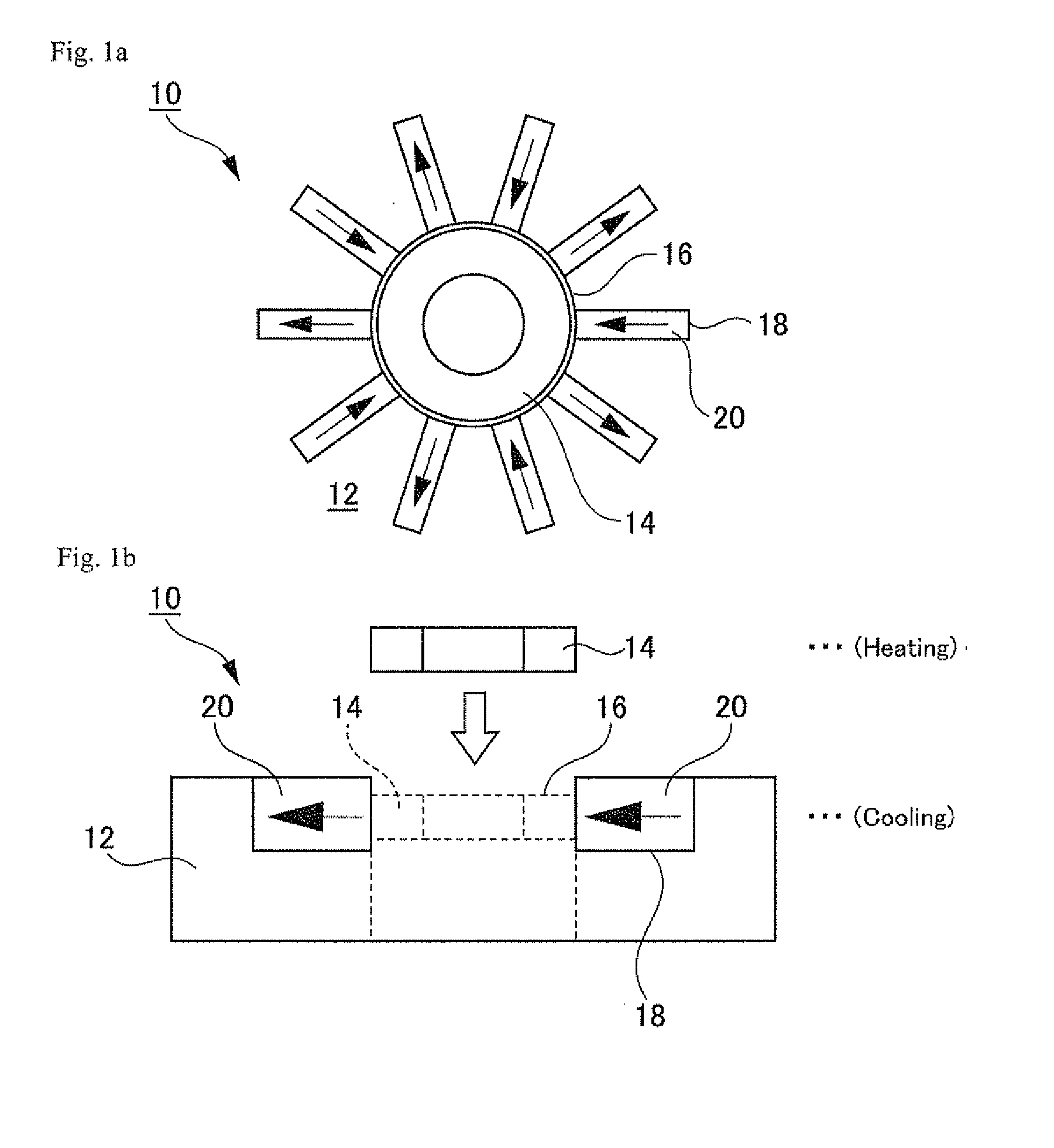
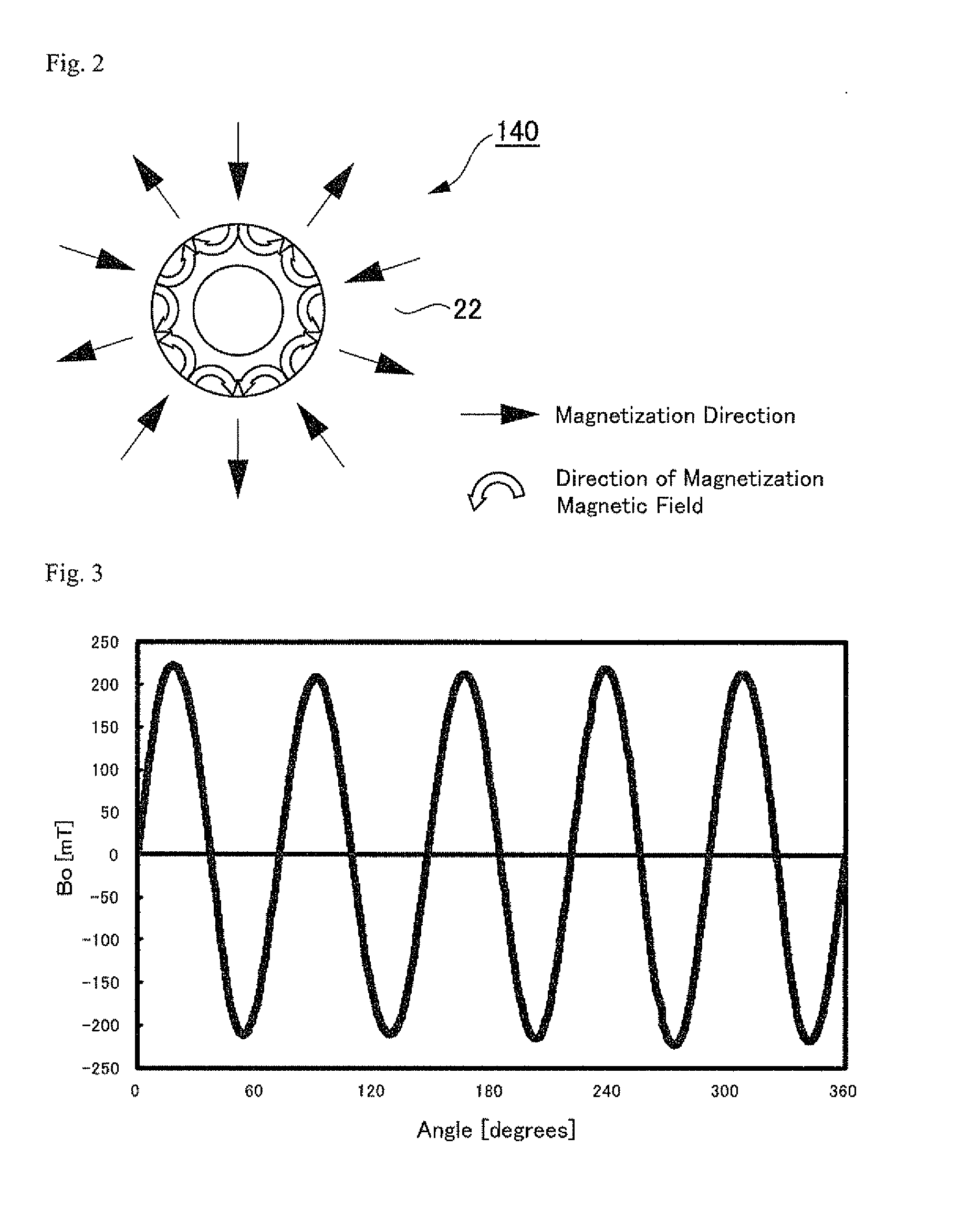
A method for manufacturing a magnetized bonded magnet, including the steps of: arranging a magnetization permanent magnet for magnetizing a magnetic field near a non-magnetized bonded magnet; heating the non-magnetized bonded magnet to a temperature of a Curie point thereof or higher; and continuously magnetizing the magnetic field to the non-magnetized bonded magnet by the magnetization permanent magnet for magnetizing the magnetic field while cooling the non-magnetized bonded magnet reached at the temperature of the Curie point thereof or higher to a temperature of less than the Curie point, wherein the non-magnetized bonded magnet is a rare-earth iron bonded magnet including two or more different rare-earth elements in magnet powder thereof.
Description
TECHNICAL FIELD[0001]The present invention relates to a method for manufacturing a bonded magnet, in particular, a magnetized bonded magnet.BACKGROUND ART[0002]In recent years, in response to remarkable downsizing of electronic apparatuses, stepping motors and the like which are used in these apparatuses have been also miniaturized and reduced in diameter. With this, ring-shaped permanent magnets which are used as rotor have been also reduced in diameter. Thus, a magnetization pitch (a magnetization distance between poles) becomes narrow, causing a difficulty in multi-pole magnetization.[0003]As a method for multi-pole magnetization, pulse magnetization is known in the art. In the pulse magnetization, when magnetizing a ring-shaped permanent magnet, a large pulse current is applied to a magnet wire. When a magnetization pitch becomes narrow with a reduction in diameter of ring-shaped permanent magnet, in magnetization fixtures under present circumstances, magnetic wires have smaller...
Claims
Login to View More Application Information
Patent Timeline
 IPC IPC(8): H01F41/02
CPCH01F13/003H01F41/028
Inventor KOMURA, HARUHIROMENJO, NOBORUSUZUKI, TOSHINORI
Owner MINEBEA CO LTD
Features
- R&D
- Intellectual Property
- Life Sciences
- Materials
- Tech Scout
- Unparalleled Data Quality
- Higher Quality Content
- 60% Fewer Hallucinations
Learn More Browse by: Latest US Patents, China's latest patents, Technical Efficacy Thesaurus, Application Domain, Technology Topic, Popular Technical Reports.
© 2025 PatSnap. All rights reserved.Legal|Privacy policy|Modern Slavery Act Transparency Statement|Sitemap|About US| Contact US: help@patsnap.com


