Magnetic recording medium for high density recording

a recording medium and high density technology, applied in the field of magnetic recording medium, can solve the problems of limited noise reduction and thermal stability degradation, and achieve the effects of reducing the aging change caused by thermal fluctuation and improving the bit error ra

Inactive Publication Date: 2006-12-28
WESTERN DIGITAL TECH INC
View PDF11 Cites 10 Cited by
  • Summary
  • Abstract
  • Description
  • Claims
  • Application Information

AI Technical Summary

Benefits of technology

[0012] According to the present invention, the bit error rate can be improved and, at the same time, the aging change caused by thermal fluctuation can be reduced.

Problems solved by technology

Since an extreme miniaturization of the crystal grains used for the magnetic recording layer or large reduction of the Brt results in the degradation of the thermal stability, the reduction of noise is limited.

Method used


Image

  • Magnetic recording medium for high density recording
  • Magnetic recording medium for high density recording
  • Magnetic recording medium for high density recording

Examples


embodiment 1

[0029]FIG. 1 shows a cross sectional structure of Embodiment 1 of a magnetic recording medium of the present invention. An aluminosilicate glass substrate 10 chemically reinforced at the surface was put to alkali cleaning. After drying, an argon (Ar) gas was introduced in vacuum, and a Ti-40 at. % Co-10 at. % Ni alloy formed by adding 40 atomic % (hereinafter referred to as at. %) cobalt and 10 at. % nickel to titanium of 14 nm thick as a first underlayer 11, and a W-30 at. % Co alloy layer of 3 nm thick comprising tungsten (W) as a main component as a second underlayer were formed by a DC magnetron sputtering method at room temperature. Then, after heating the substrate to reach a temperature of about 400° C. in an atmosphere with residual gas being controlled by a lamp heater, a Cr-10 at. % Ti-3 at. % B alloy of 10 nm thick was formed as a third underlayer 13. Further, a first magnetic layer 14 of 2.5 nm thick comprising a Co-14 at. % Cr-6 at. % Pt alloy, a first non-magnetic inte...

embodiment 2

[0046]FIG. 7 shows a constitutional cross-sectional view of a medium examined in this embodiment. A magnetic recording medium was formed in the same manner as in Embodiment 1 except that the following conditions were changed among the conditions for manufacturing Embodiment 1.

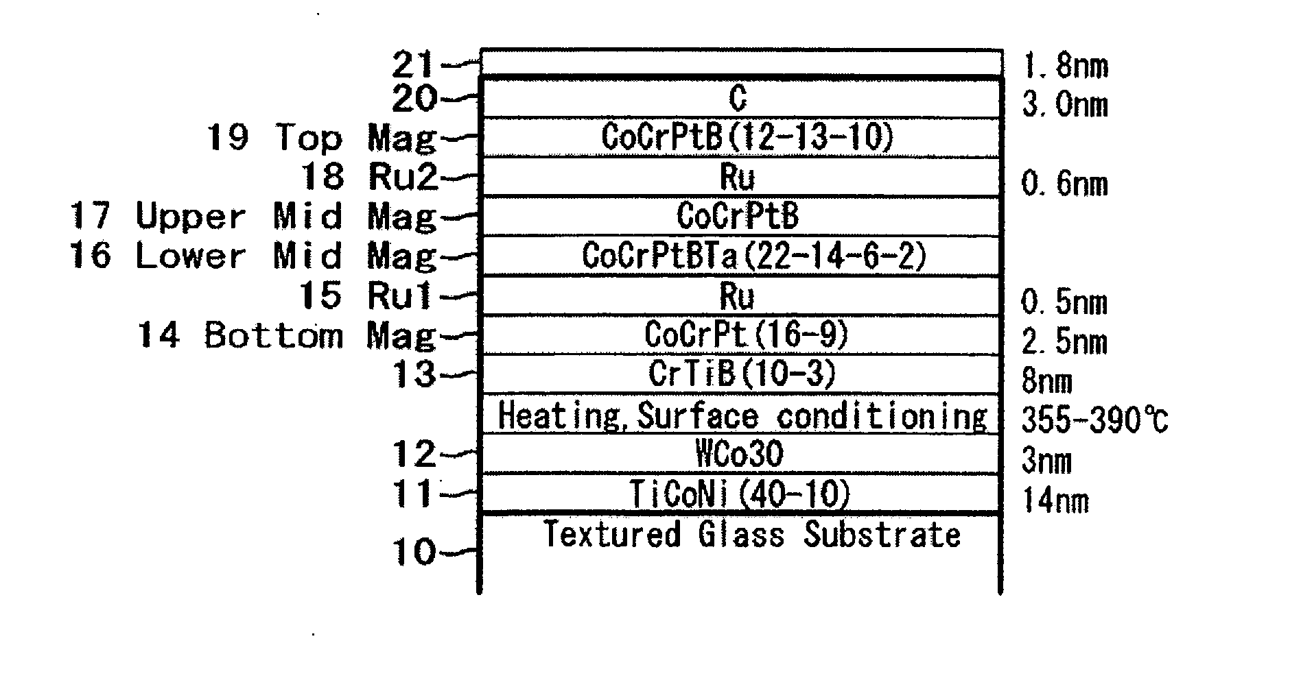
[0047] (1) To control the coercivity, the heating temperature for the substrate was used as a variant, which was controlled from 350° C. to 390° C.

[0048] (2) The thickness of Ru formed as the first intermediate layer was set to about 0.5 nm.

[0049] (3) The thicknesses of the second magnetic layer and the third magnetic layer were changed.

[0050] (4) The composition and the thickness of the fourth magnetic layer were changed.

[0051] (5) The thickness of Ru formed between the third magnetic layer and the fourth magnetic layer was fixed at about 0.6 nm.

[0052] A combination of the thickness for the second magnetic layer (Co-22 at. % Cr-14 at. % Pt-6 at. % B-2 at. % Ta) and the third magnetic layer (Co-12 at. % C...

embodiment 3

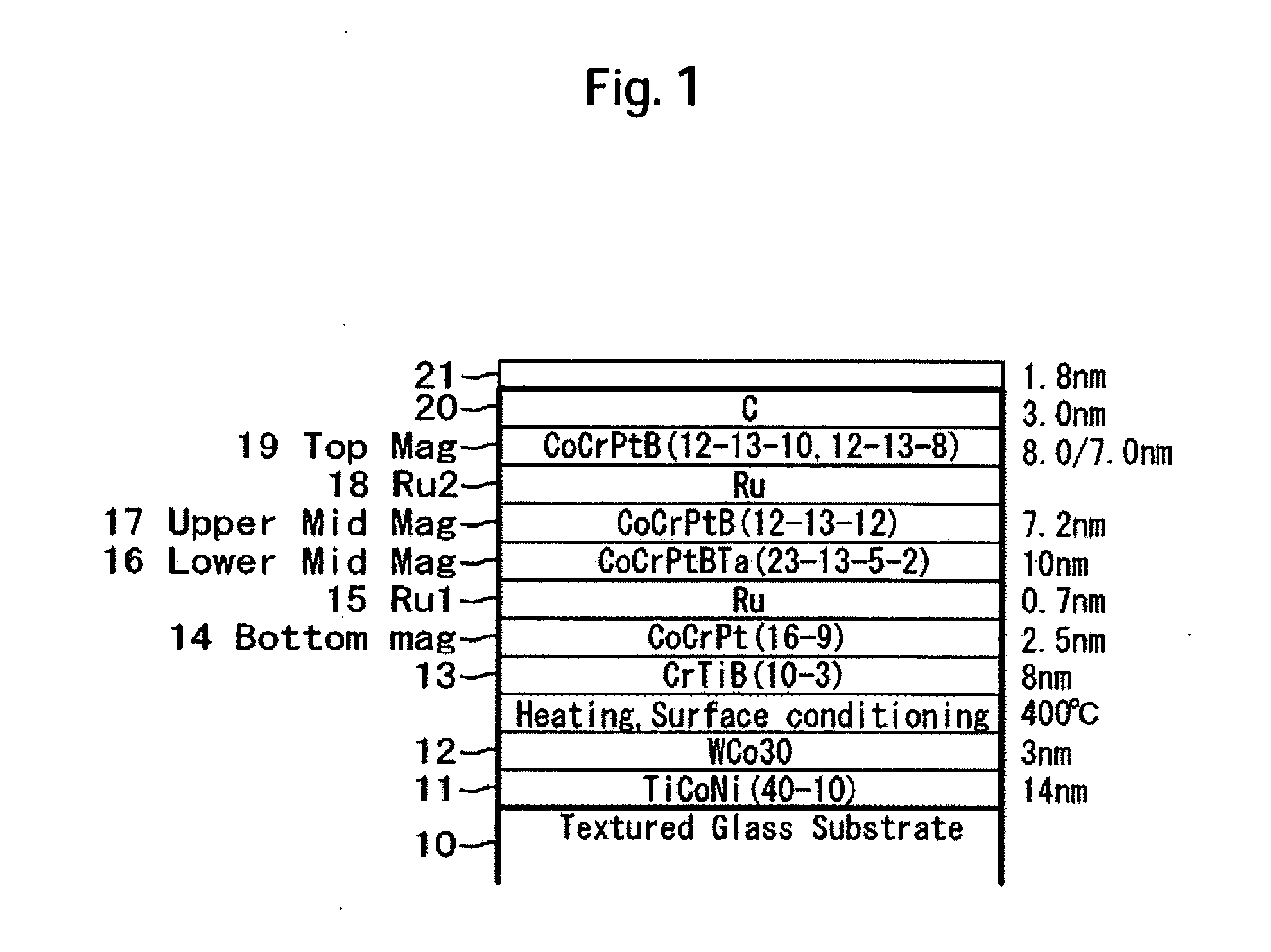
[0059]FIG. 10 shows a constitutional cross-sectional view of a medium examined in this embodiment. A magnetic recording medium is formed in the same manner as in Embodiment 2 except that the following conditions are changed among the conditions for manufacturing Embodiment 2.

[0060] (1) The composition and thickness of the third magnetic layer are changed.

[0061] (2) The fourth magnetic layer is fixed to a Co-12 at. % Cr-13 at. % Pt-10 at. % B alloy.

[0062] The thickness of the second magnetic layer: Co-22 at. % Cr-14 at. % Pt-6 at. % B-2 at. % Ta included two types of 11.7 nm and 10.6 nm. As the composition for the third magnetic layer, Co-8 at. % Cr-13 at. % Pt-12 at. % B, Co-10 at. % Cr-13 at. % Pt-12 at. % B, Co-12 at. % Cr-13 at. % Pt-12 at. % B, Co-14 at. % Cr-13 at. % Pt-12 at. % B, Co-12 at. % Cr-13 at. % Pt-10 at. % B, and Co-12 at. % Cr-13 at. % Pt-14 at. % B were examined.

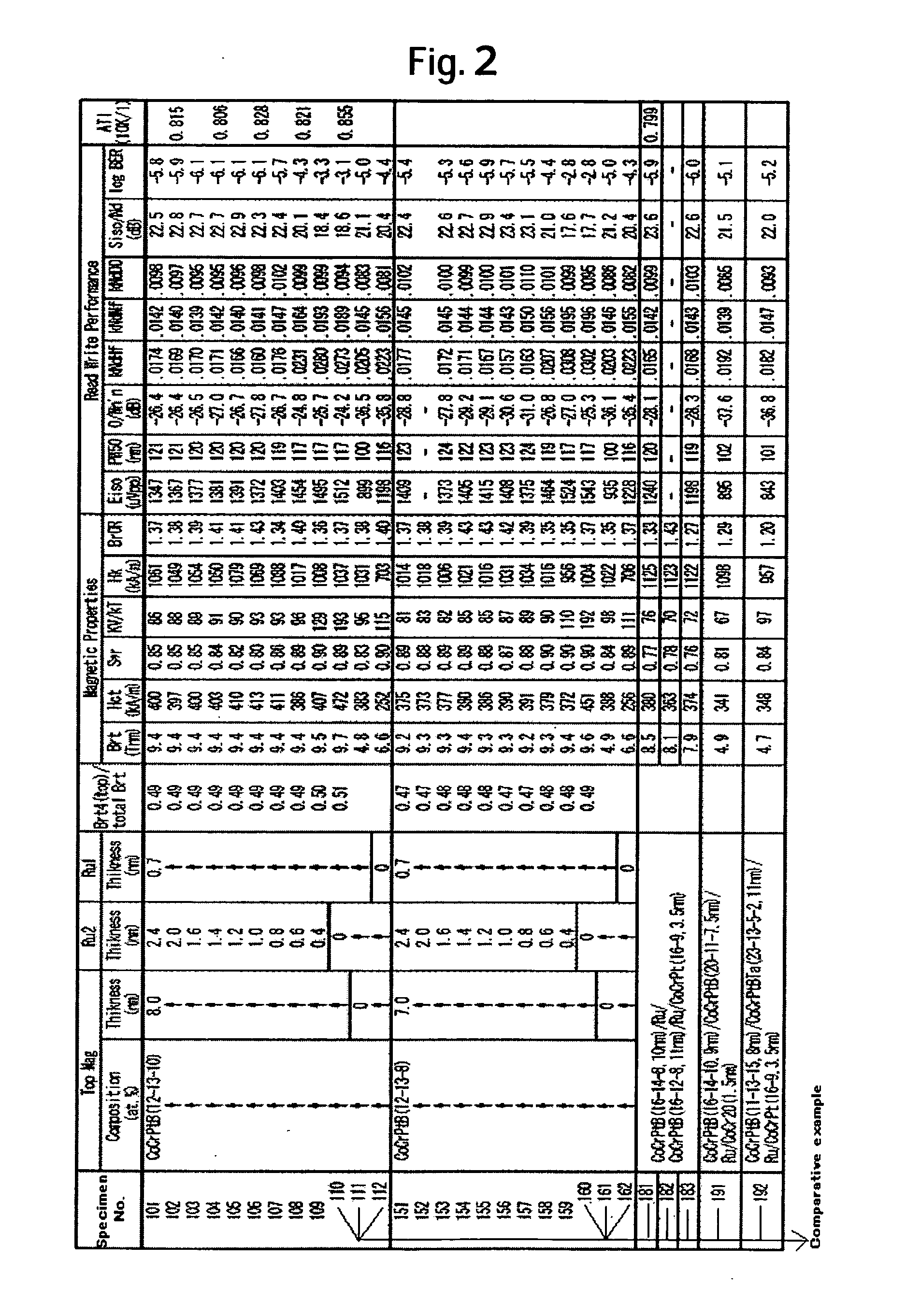
[0063]FIG. 11 shows the relationship between the magnetic characteristic and electromagnetic convers...


PUM

PropertyMeasurementUnit
thicknessaaaaaaaaaa
thicknessaaaaaaaaaa
thickaaaaaaaaaa

Abstract

A bit error rate is improved and, at the same time, an aging change due to thermal fluctuation is decreased. In one embodiment, a magnetic recording medium has first, second, third, and fourth magnetic layers stacked over the underlayer film on a substrate. The product (Brt2) of the residual magnetic flux density and film thickness of the second magnetic layer is smaller than the product (Brt3) of the residual magnetic flux density and film thickness of the third magnetic layer. The second magnetic layer has a thickness larger than that of the third magnetic layer and is anti-ferromagnetically coupled with the first magnetic layer by way of the first non-magnetic intermediate layer. The fourth magnetic layer is formed by way of a second non-magnetic intermediate layer above the third magnetic layer. The product (Brt4) of the residual magnetic flux density and film thickness of the fourth magnetic layer is from about 47% to 52% of the product (Brt_total) of the residual magnetic flux density and film thickness of the entire magnetic layers in a state of residual magnetization with the external magnetic field removed.

Description

CROSS-REFERENCES TO RELATED APPLICATIONS [0001] This application claims priority from Japanese Patent Application No. JP2005-184375, filed Jun. 24, 2005, the entire disclosure of which is incorporated herein by reference. BACKGROUND OF THE INVENTION [0002] The present invention relates to a magnetic recording medium capable of recording a great amount of information and, more in particular, it relates to a magnetic recording medium suitable for high-density magnetic recording. [0003] There has been an increasing demand for magnetic storage apparatus typically represented by magnetic disk apparatus with a greater capacity. In order to cope with the demand, a development has been required for a magnetic head with high sensitivity and a recording medium capable of obtaining high signal output-to-noise ratio (S / N). [0004] Generally, a recording medium comprises a first underlayer referred to as a seed layer formed over a substrate, a second underlayer of a body-centered cubic structure ...

Claims


Application Information

Patent Timeline
Patent Type & Authority Applications(United States)
IPC IPC(8): G11B5/66
CPCG11B5/656G11B5/7325G11B5/66G11B5/7368
Inventor SUZUKI, HIROYUKIKASHIWASE, HIDEKAZUMORINAGA, AKIRAHINOUE, TATSUYA
Owner WESTERN DIGITAL TECH INC
Why Eureka
Try Eureka