Composite Tank Having Joint with Softening Strip and Method of Making the Tank

a technology of composite tanks and joints, applied in the field of composite structures, can solve the problems of unacceptably high joint peak stress levels, joint leakage, and many other conventional materials that may not remain soft, but instead harden, and achieve linear joint stress, reduce joint peak stress levels

Active Publication Date: 2013-08-01
THE BOEING CO
View PDF7 Cites 11 Cited by
  • Summary
  • Abstract
  • Description
  • Claims
  • Application Information

AI Technical Summary

Benefits of technology

[0009]The disclosed embodiments provide a composite structure such a tank suitable for use in cryogenic environments. The tank may be used in space exploration and launch vehicles to contain liquids such as propellants at cryogenic temperatures. The tank may include a cylindrical tank wall attached to domed ends by bonded overlapping joints. The embodiments include a softening strip located in each of the joints for reducing peak stresses in joint. The softening strip remains soft, flexible and compliant at cryogenic temperatures. The softening strip linearizes the stress in the joint caused by the transfer of line loads through the joint, and remains stable at the temperatures at which thermosetting resins used in the tank wall and domes are cured.

Problems solved by technology

In composite cryogenic tanks of larger diameters, e.g. diameters of greater than approximately than 14 to 16 feet, the line loads in the bonded joints may result in unacceptably high levels of peak stresses in the joint, presenting the possibility of a joint leak.
This could be accomplished at ambient temperatures using a softening strip formed of a material such as rubber, however, at cryogenic temperatures, rubber and many other conventional materials may not remain soft, but instead harden.
Upon hardening at cryogenic temperatures, the softening strip may no longer be capable of controlling shear stress in the joint.
Known materials that may be used as softening strips present several other problems in cryogenic environments.
For example, such materials typically have a coefficient of thermal expansion (CTE) that may be incompatible with other composite components of the joint which have a relatively low CTE.
This mis-match of CTE's may create undesirable thermally-induced stresses in the joint at cryogenic temperatures.

Method used


Image

  • Composite Tank Having Joint with Softening Strip and Method of Making the Tank
  • Composite Tank Having Joint with Softening Strip and Method of Making the Tank
  • Composite Tank Having Joint with Softening Strip and Method of Making the Tank

Examples


Embodiment Construction

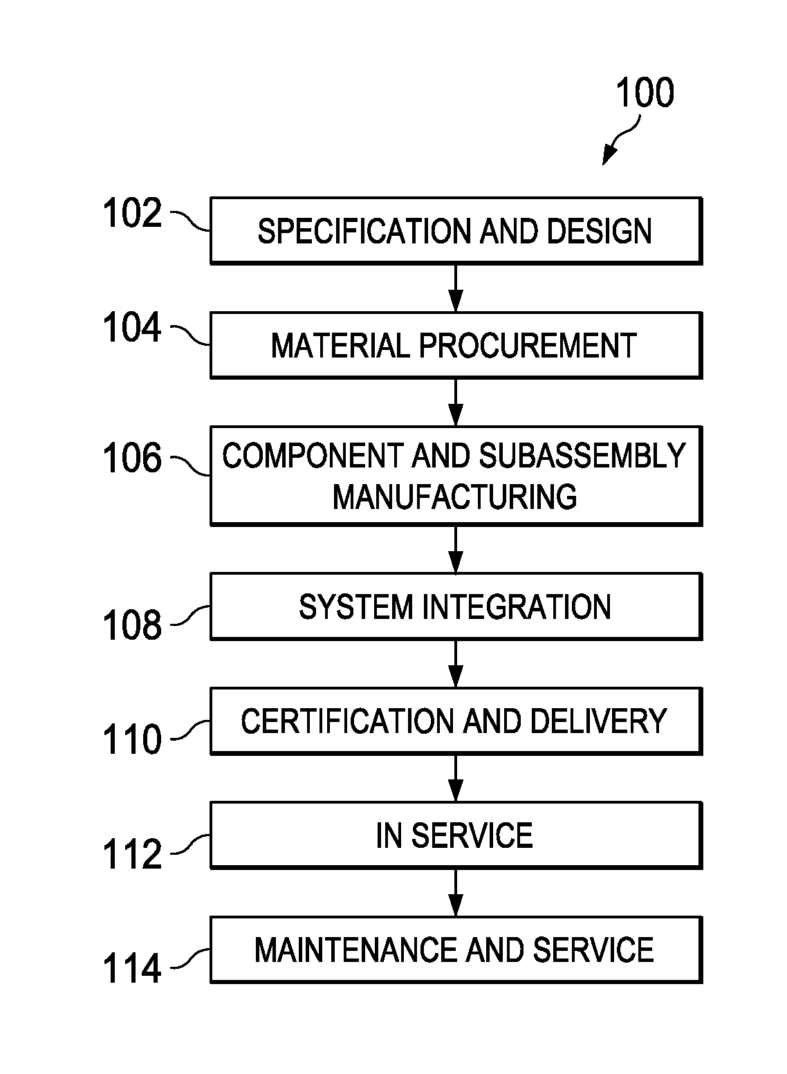
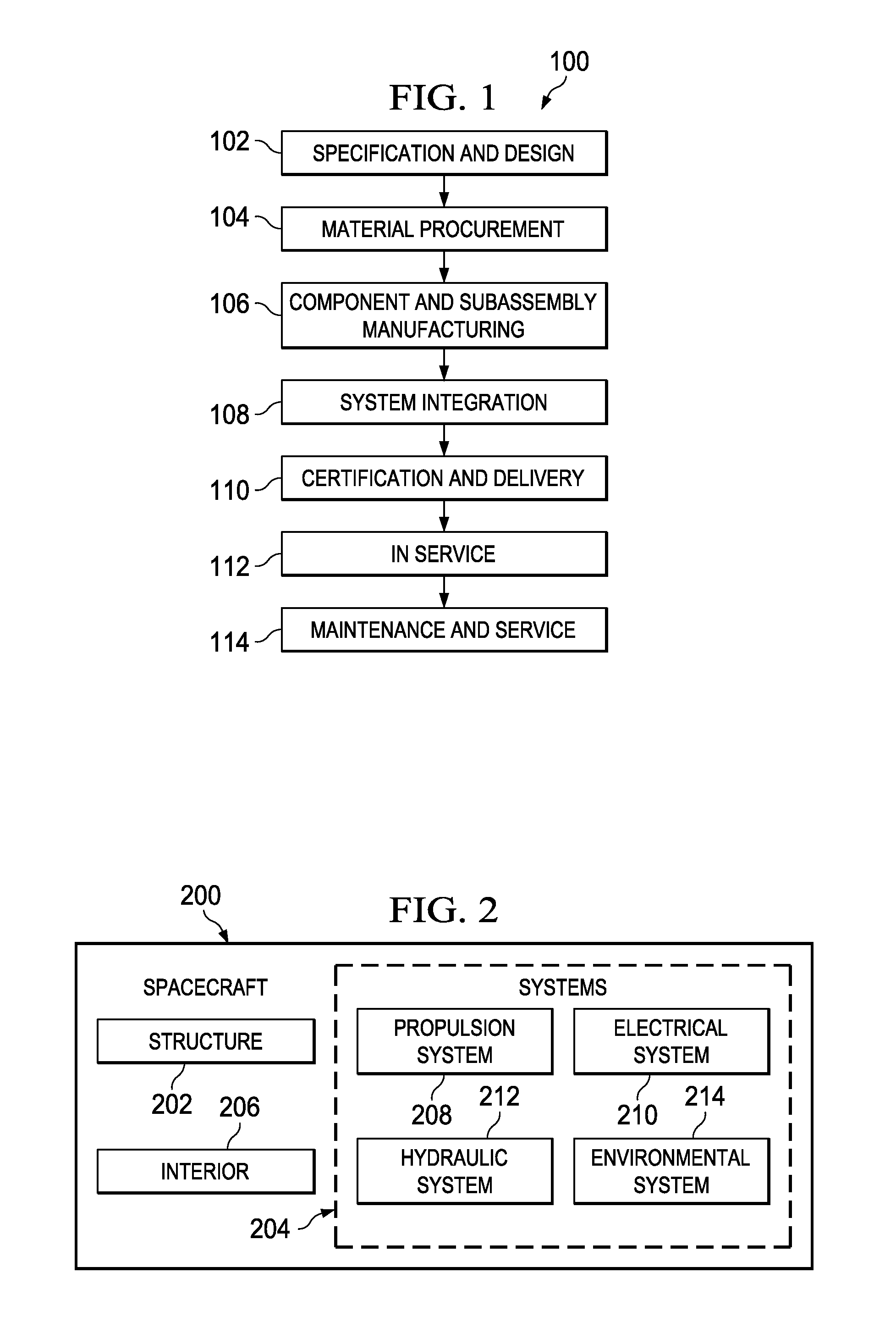
[0037]Referring more particularly to the drawings, embodiments of the disclosure may be described in the context of the spacecraft manufacturing and service method 100 as shown in FIG. 1 and spacecraft 200 as shown in FIG. 2. Turning first to FIG. 1, a diagram illustrating a spacecraft manufacturing and service method is depicted in accordance with one disclosed embodiment.

[0038]During pre-production, exemplary spacecraft manufacturing and service method 100 may include specification and design 102 of spacecraft 200 in FIG. 2 and material procurement 104. During production, component and subassembly manufacturing 106 and system integration 108 of spacecraft 200 in FIG. 2 takes place. Thereafter, spacecraft 200 in FIG. 2 may go through certification and delivery 110 in order to be placed in service 112. While in service by a customer, spacecraft 200 in FIG. 2 is scheduled for routine maintenance and service 114, which may include modification, reconfiguration, refurbishment, and othe...


PUM

PropertyMeasurementUnit
diameteraaaaaaaaaa
diameteraaaaaaaaaa
temperaturesaaaaaaaaaa

Abstract

A composite resin tank includes a wall joined to a dome along a joint. A softening strip is located in the joint.

Description

CROSS REFERENCE TO RELATED APPLICATIONS[0001]This application is a continuation-in-part of U.S. patent application Ser. No. 12 / 175,735 filed Jul. 18, 2008, the entire disclosure of which is incorporated by reference herein. This application is also related to a U.S. patent application entitled “Device for Controlling Stress in Joints at Cryogenic Temperatures and Method of Making the Same,” U.S. patent application Ser. No. 13 / 541,534, attorney docket 12-0149-US-CIP, filed even date herewith.BACKGROUND INFORMATION[0002]1. Field[0003]The present disclosure generally relates to composite structures that are subjected to cryogenic temperatures, and deals more particularly with a tank used in space exploration and launch vehicles to contain liquids such as propellants at cryogenic temperatures.[0004]2. Background[0005]Certain structures may be specifically designed for use in cryogenic environments. For example, spacecraft and launch vehicles may employ tanks to store solid propellants o...

Claims


Application Information

Patent Timeline
Patent Type & Authority Applications(United States)
IPC IPC(8): B65D90/02B32B37/14
CPCB64G1/002B64G1/402B64G1/66D04H13/00B64G1/64D04H13/002
Inventor ROBINSON, MICHAEL J.HAND, MICHAEL LESLIEBLEVINS, CREED ERNEST
Owner THE BOEING CO
Why Eureka
Try Eureka