Terminal Box

a terminal plate and box body technology, applied in the field of terminal boxes, can solve the problems of unlikely impairment of electrical and mechanical performance at the locations of connecting terminal parts and the terminal plates, and reduce the efficiency of conduction so as to reduce the reduce the effect of heat of melting solder to the terminal plates

Inactive Publication Date: 2013-08-01
HOSIDEN CORP
View PDF1 Cites 4 Cited by
  • Summary
  • Abstract
  • Description
  • Claims
  • Application Information

AI Technical Summary

Benefits of technology

[0009]In the terminal box of the present configuration, the existence of the slit formed along the outer perimeter of the region on which the first terminal part is laid allows the conduction of the heat of the melting solder to the terminal plates to be minimized. Additionally, the occurrence of melting solder flowing out toward the terminal plate from the location connecting the first terminal part and the terminal plate can be minimized.
[0010]Therefore, if a terminal box has the present configuration, the conduction of the heat of melting solder to the terminal plates can be efficiently minimized, and the electrical and mechanical performance at locations connecting the terminal parts and the terminal plates is also unlikely to be impaired.

Problems solved by technology

Therefore, if a terminal box has the present configuration, the conduction of the heat of melting solder to the terminal plates can be efficiently minimized, and the electrical and mechanical performance at locations connecting the terminal parts and the terminal plates is also unlikely to be impaired.

Method used


Image

  • Terminal Box
  • Terminal Box
  • Terminal Box

Examples


Embodiment Construction

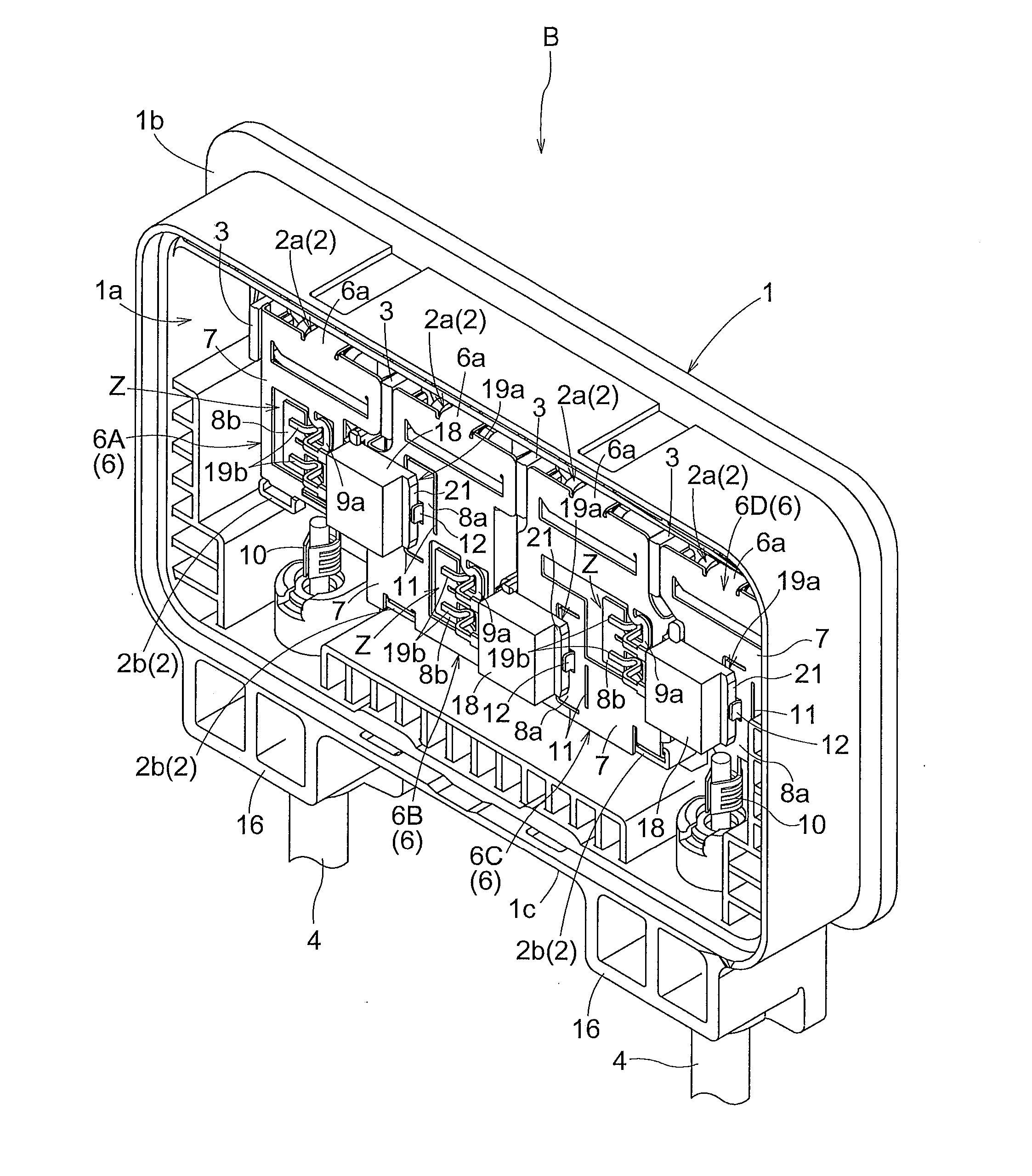
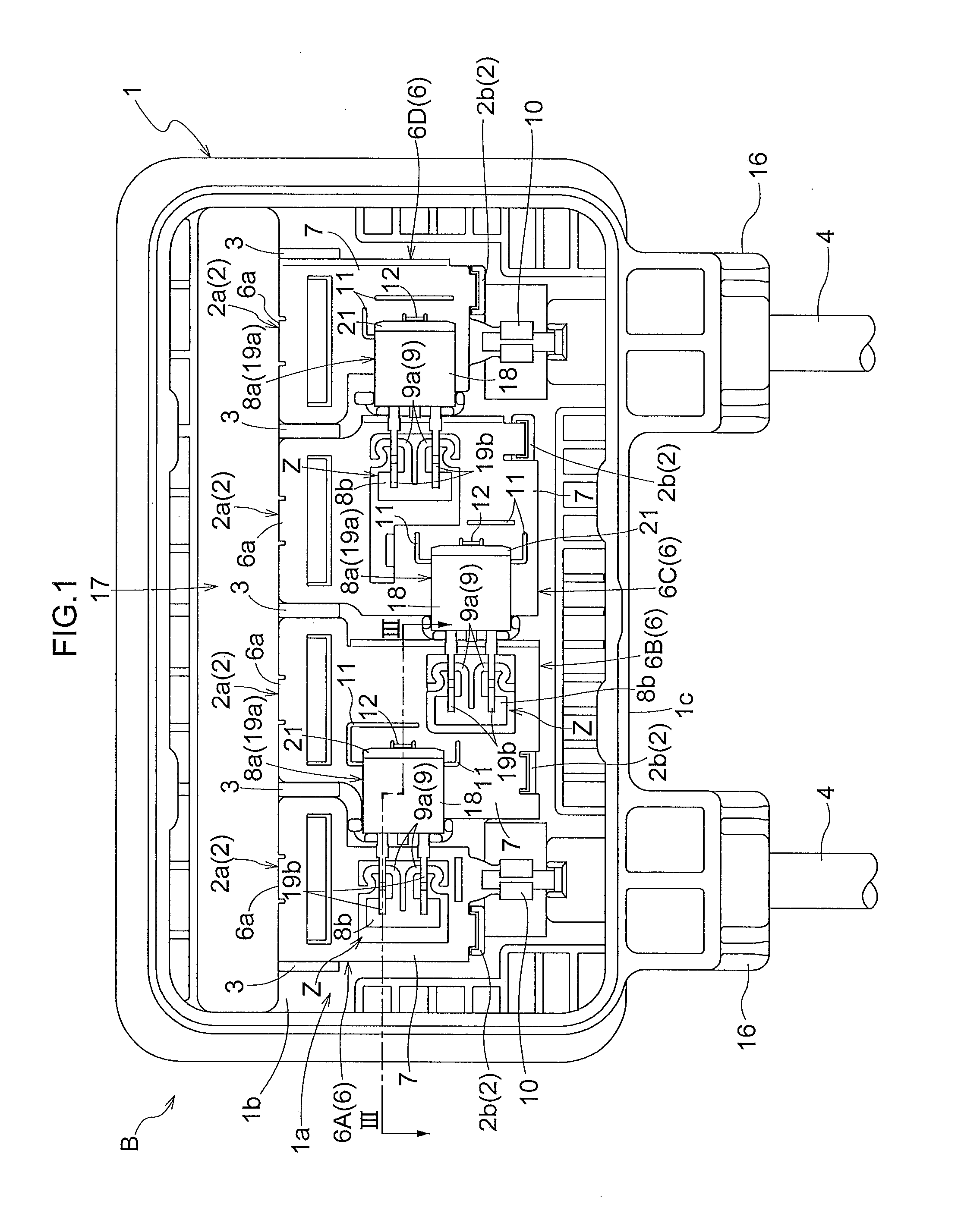
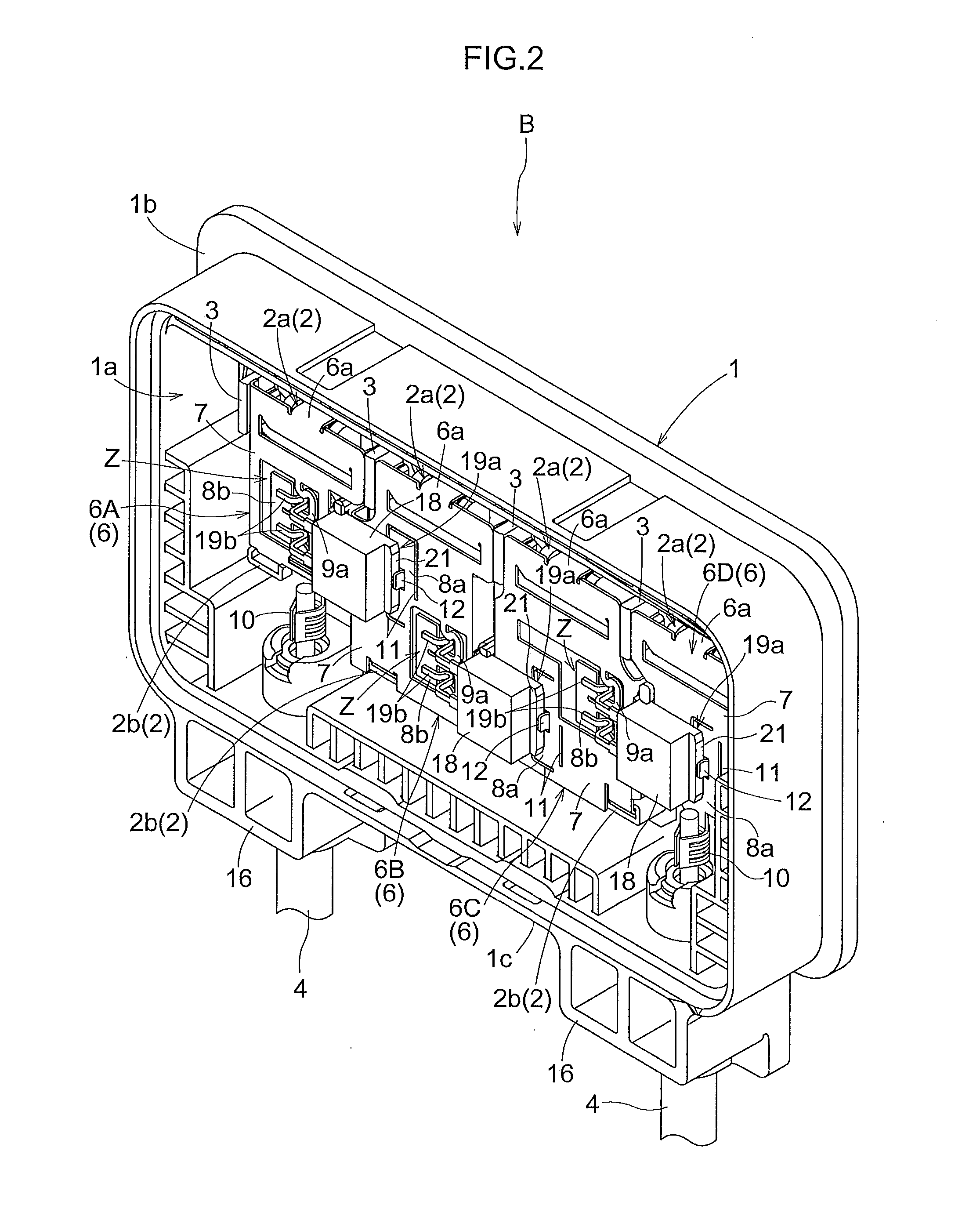
[0027]Embodiments of the present invention will be described below on the basis of the drawings. FIGS. 1 and 2 show a terminal box B that is connected to a photovoltaic module. The terminal box B has an aperture part 1a, a bottom plate 1b, and lateral plates 1c, and is provided with a rectangular box-shaped box body 1, which is made of resin, and a lid (not shown), which covers the aperture part 1a of the box body 1 and is made of resin. In the interior of the box body 1, four terminal plates 6 (6A through 6D) that are electrically connected to the photovoltaic module (not shown) are arranged in a row.

[0028]Two types of holding parts 2 (2a, 2b) for latching to and holding the terminal plates 6, and a holding wall 3 for contacting and positioning the edge parts of the terminal plates 6 are provided to positions corresponding to each of the terminal plates 6. A terminal-lead-in hole 17 into which output terminals (not shown) of the photovoltaic module are led is formed through the bot...


PUM


Abstract

A plurality of terminal plates are arranged in a row in the interior of a box body. Neighboring terminal plates are electrically connected by a diode. The diode is provided with a first terminal part that is laid on, soldered to, and electrically connected to the first terminal plate. A slit is provided formed along the outer perimeter of a region on which the first terminal part is laid on the first terminal plate.

Description

BACKGROUND OF THE INVENTION[0001]1. Field of the Invention[0002]The present invention relates to a terminal box provided with a plurality of terminal plates, which are arranged in a row within a box body, and a diode for electrically connecting the terminal plates, where the diode is provided with terminal parts that are laid on the terminal plates and electrically connected thereto by soldering.[0003]2. Description of the Related Art[0004]In the aforedescribed terminal box, when the terminal parts of the diode are laid on the terminal plates and soldered, the heat of the melting solder is conducted to the terminal plates, large amounts of heat are discharged, and the time required to heat the solder tends to increase. Therefore, in addition to longer periods of time required for soldering, the diode is excessively heated by the heat conducted from the terminal parts, and the performance of the diode may be impaired.[0005]In order to prevent this situation, in a conventional termina...

Claims


Application Information

Patent Timeline
Patent Type & Authority Applications(United States)
IPC IPC(8): H01L23/367
CPCH01L23/057H01L23/32H01L31/0485H05K7/005Y02E10/50H01L2924/0002H01L23/367H02S40/34H01L2924/00
Inventor YAMAZAKI, MASAKAZU
Owner HOSIDEN CORP
Why Eureka
Try Eureka