Power amplifier, radio-frequency power amplification device, and amplification control method

Active Publication Date: 2013-08-01
NEC CORP
View PDF1 Cites 21 Cited by
  • Summary
  • Abstract
  • Description
  • Claims
  • Application Information

AI Technical Summary

Benefits of technology

[0048]By using the present invention, amplification wi

Problems solved by technology

Therefore, it is difficult to improve the power efficiency of the power ampli

Method used


Image

  • Power amplifier, radio-frequency power amplification device, and amplification control method
  • Power amplifier, radio-frequency power amplification device, and amplification control method
  • Power amplifier, radio-frequency power amplification device, and amplification control method

Examples


Example

First Exemplary Embodiment

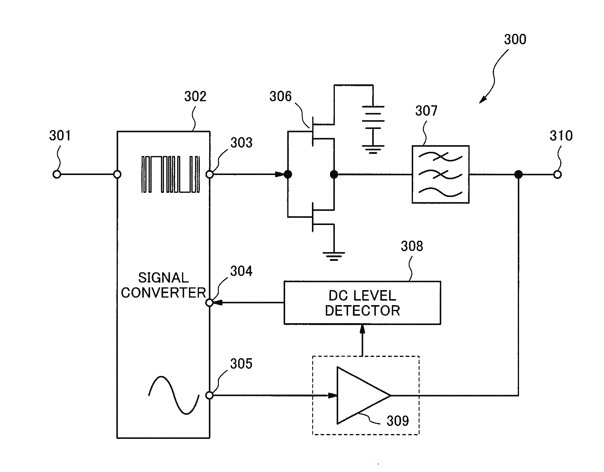
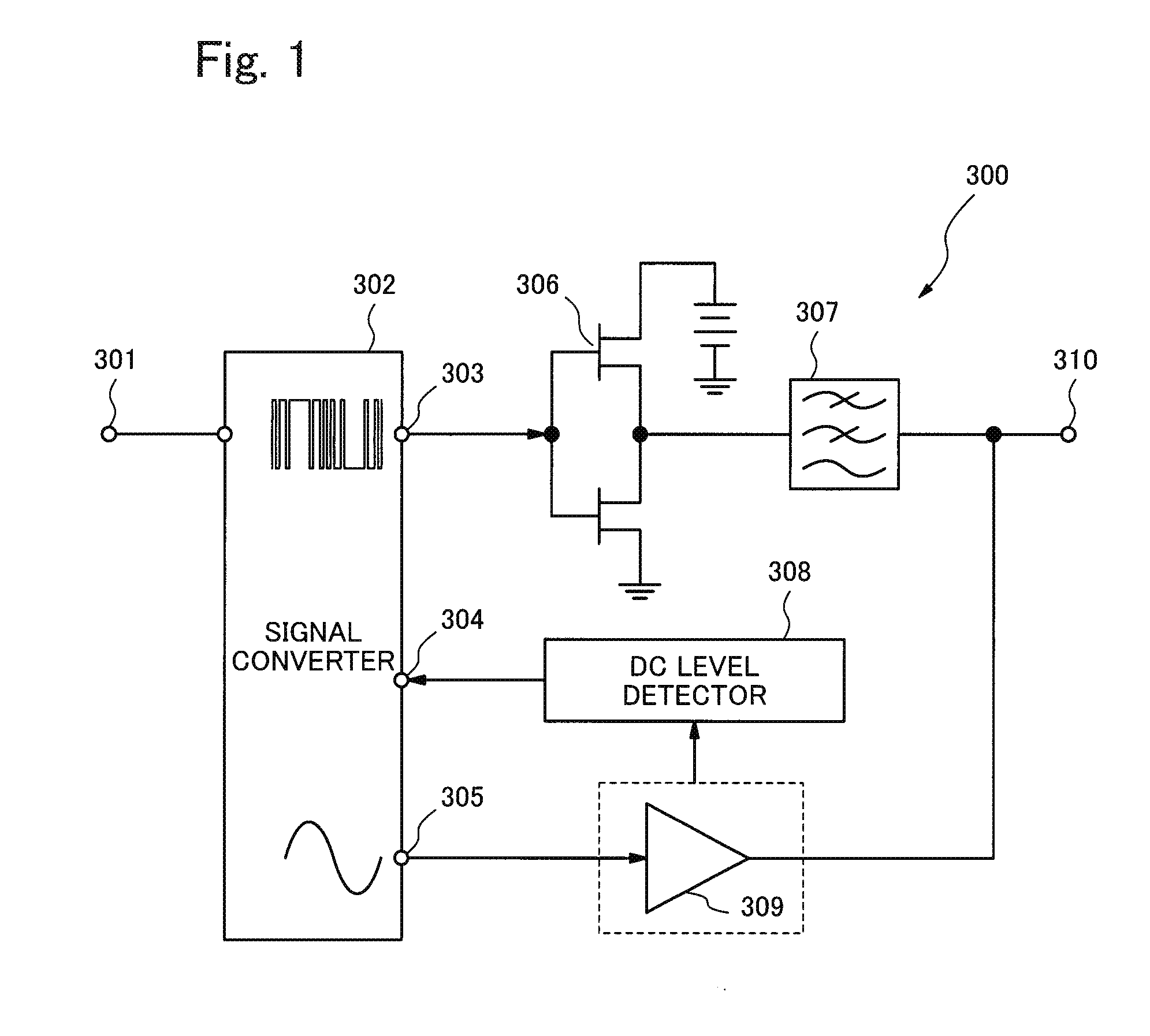
[0066]FIG. 1 is a block diagram showing an example of a configuration of a power amplifier 300 according to a first exemplary embodiment of the present invention. The power amplifier 300 comprises a signal input terminal 301, a signal converter 302 (signal conversion block), a digital signal output terminal 303, a DC (Direct Current) feedback terminal 304, and an analog signal output terminal 305. Further, the power amplifier 300 comprises a switching amplifier 306, a low pass filter 307, a DC level detector 308 (DC level detection block), a linear amplifier 309, and a signal output terminal 310.

[0067]A signal that is an amplification target is inputted through the signal input terminal 301. The signal converter 302 generates a digital signal amplified by the switching amplifier 306 and an analog signal amplified by the linear amplifier 309 from the signal inputted through the signal input terminal 301 based on a predetermined signal generation parameter. I...

Example

Second Exemplary Embodiment

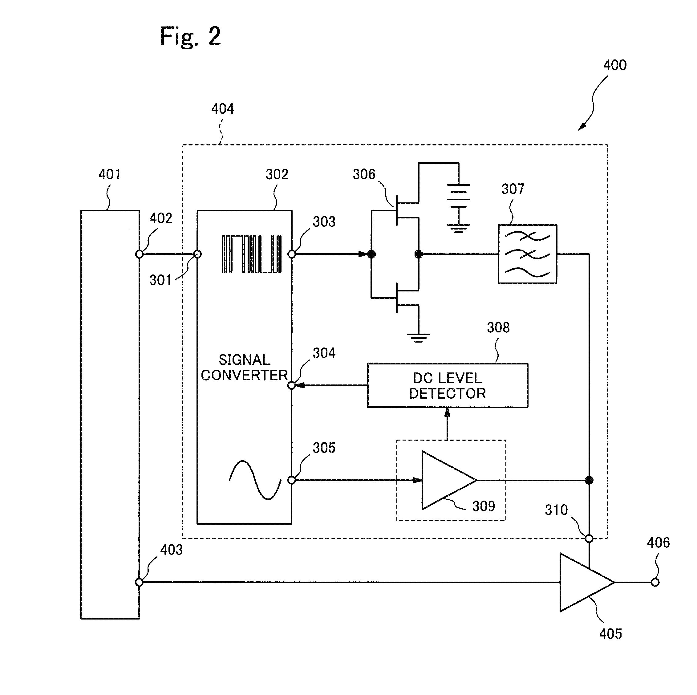
[0074]FIG. 2 is a block diagram showing an example of a configuration of a radio-frequency power amplification device 400 according to a second exemplary embodiment of the present invention. The radio-frequency power amplification device 400 comprises a baseband signal conversion circuit 401, an amplitude signal output terminal 402, a first radio-frequency modulation signal output terminal 403, a second radio-frequency modulation signal output terminal 406, a power supply modulator 404, and a radio-frequency power amplifier 405. The configuration of the power supply modulator 404 is the same as that of the power amplifier 300 of the first exemplary embodiment.

[0075]The baseband signal conversion circuit 401 outputs a radio-frequency modulation signal obtained by converting a baseband signal through the first radio-frequency modulation signal output terminal 403 and outputs the amplitude modulation component of the radio-frequency modulation signal through ...

Example

Third Exemplary Embodiment

[0078]FIG. 3 is a block diagram showing an example of a configuration of a power amplifier 500 according to a third exemplary embodiment of the present invention. The power amplifier 500 comprises a signal input terminal 501, the signal converter 302, a linear amplifier module 503, a switching amplifier module 504, and a signal output terminal 505.

[0079]The input signal that is the amplification target is inputted through the signal input terminal 501. The signal converter 302 comprises a signal distributor 502 (signal distribution block) and a 1-bit signal generator 510. The signal distributor 502 divides the input signal into two signals (a first signal and a second signal). After that, after the signal distributor 502 adjusts an amount of relative delay between two divided signals and a signal band, the signal distributor 502 outputs one signal (first signal) to the switching amplifier module 504 and outputs the other signal (second signal) to the linear...


PUM


Abstract

The present invention allows amplification with low distortion and high efficiency.
A power amplifier of the present invention comprises signal conversion means which generates a digital signal and an analog signal from an input signal that is an amplification target based on a signal generation parameter, a switching amplifier which amplifies the digital signal, a linear amplifier which amplifies the analog signal, and DC level detection means which detect a DC level of at least one of the signal amplified by the linear amplifier and the amplified signal and output a detection result to the signal conversion means, wherein the signal conversion means adjust the signal generation parameter so that the DC level inputted by the DC level detection means is virtually equal to zero.

Description

TECHNICAL FIELD[0001]The present invention relates to a power amplifier, a radio-frequency power amplification device, and an amplification control method.BACKGROUND ART[0002]A modulation scheme used for wireless communication devices such as a modern mobile phone and the like has radio-frequency utilization efficiency and a high peak-to-average power ratio (PAPR). In order to amplify a signal to which an amplitude modulation is applied by using an AB class amplifier that has been commonly used in a wireless communication field, it is necessary to use an amplifier operating with sufficient back-off to maintain a linearity. Generally, the required back-off value is at least approximately equal to a value of the PAPR. However, in the AB class amplifier, the maximum efficiency is obtained when it operates at the saturation point and the efficiency of the amplifier decreases with increasing the back-off value. Therefore, it is difficult to improve the power efficiency of the power ampli...

Claims


Application Information

Patent Timeline
IPC IPC(8): H03F3/21H03F1/02
CPCH03F1/32H03F3/211H03F3/217H03F3/245H03F1/0222H03F2200/481H03F2200/555H03F3/195H03F2200/462
Inventor TAKAHASHI, KIYOHIKO
Owner NEC CORP
Why Eureka
Try Eureka