Touch screen, touch panel, and display device including the same

a display device and touch technology, applied in the field of touch screen, touch panel, display device, can solve the problem of low capacitance of touch detection, and achieve the effect of reducing capacitan

Active Publication Date: 2013-08-01
TRIVALE TECH LLC
View PDF4 Cites 21 Cited by
  • Summary
  • Abstract
  • Description
  • Claims
  • Application Information

AI Technical Summary

Benefits of technology

[0014]An object of the present invention is to provide a technique that can reduce a capacitance between a column direction wire bunch and a row direction wire bunch.

Problems solved by technology

Accordingly, application of the mutual capacitance detection type to such a configuration causes a problem that the sensitivity of detection of a touch is low.

Method used


Image

  • Touch screen, touch panel, and display device including the same
  • Touch screen, touch panel, and display device including the same
  • Touch screen, touch panel, and display device including the same

Examples


embodiment 1

Preferred Embodiment 1

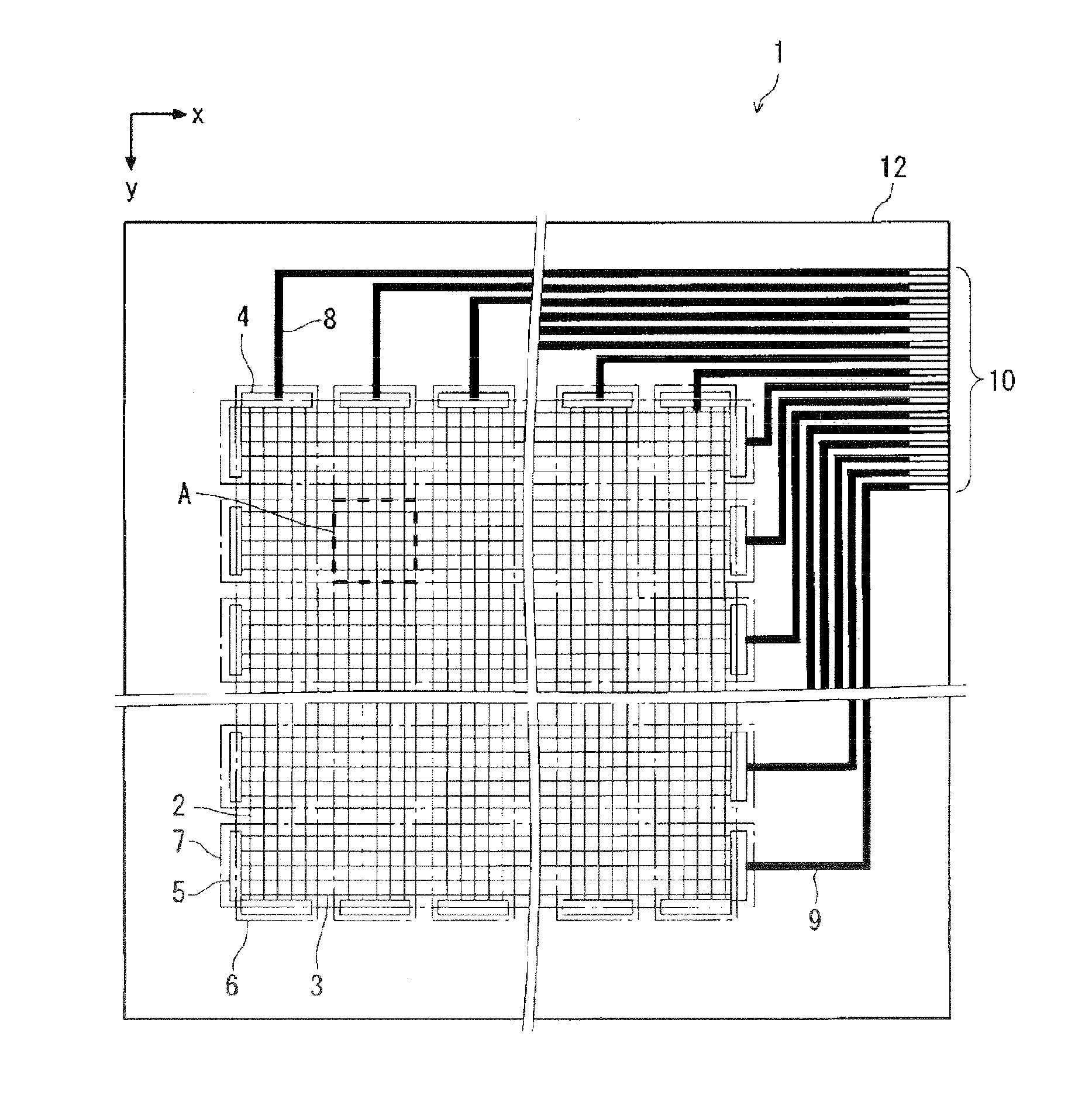
[0034]FIG. 1 is a plan view schematically showing a configuration of a touch screen 1 provided in a touch panel according to a preferred embodiment 1 of the present invention. In the following, a configuration, and the like, of the touch screen 1 according to this preferred embodiment will be described with reference to FIG. 1 and the like. Here, a reference sign given to a component part described in this preferred embodiment is also given to a component part of preferred embodiments 2 and 3 that is identical or similar to said component part of the preferred embodiment 1.

[0035]As shown in FIG. 1, the touch screen 1 includes a base substrate 12, (1) a plurality of detection column wires 2, and (2) a plurality of detection row wires 3. The base substrate 12 is a transparent substrate made of a transparent glass material or a transparent resin. The plurality of detection column wires 2 extend in a column direction (corresponding to the y direction in FIG. 1). Th...

embodiment 2

Preferred Embodiment 2

[0106]A preferred embodiment 2 of the present invention is different from the preferred embodiment 1, in terms of the shapes of the detection column wires 2 and the detection row wires 3 provided in the block regions C1, C2, R1, and R2.

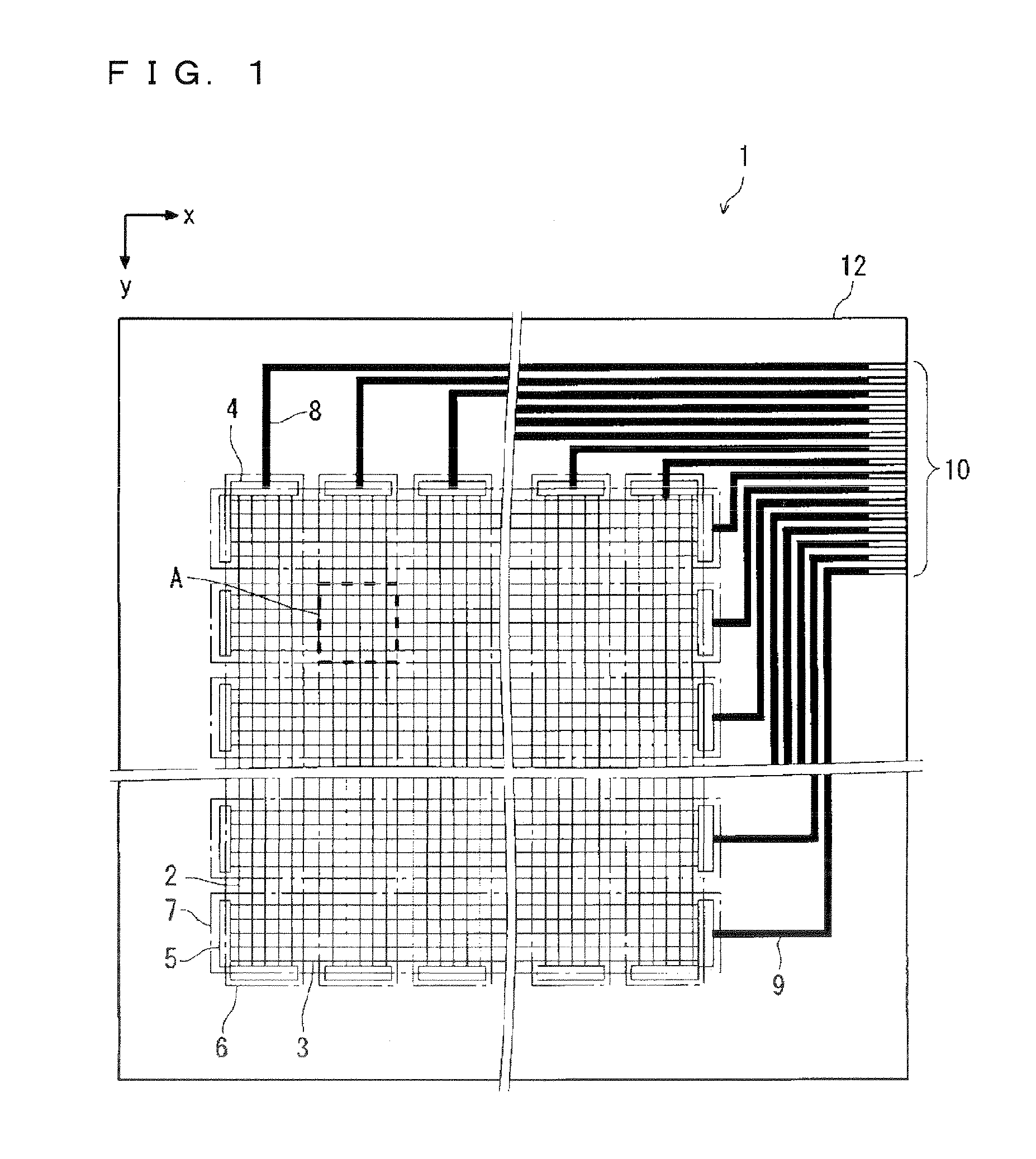
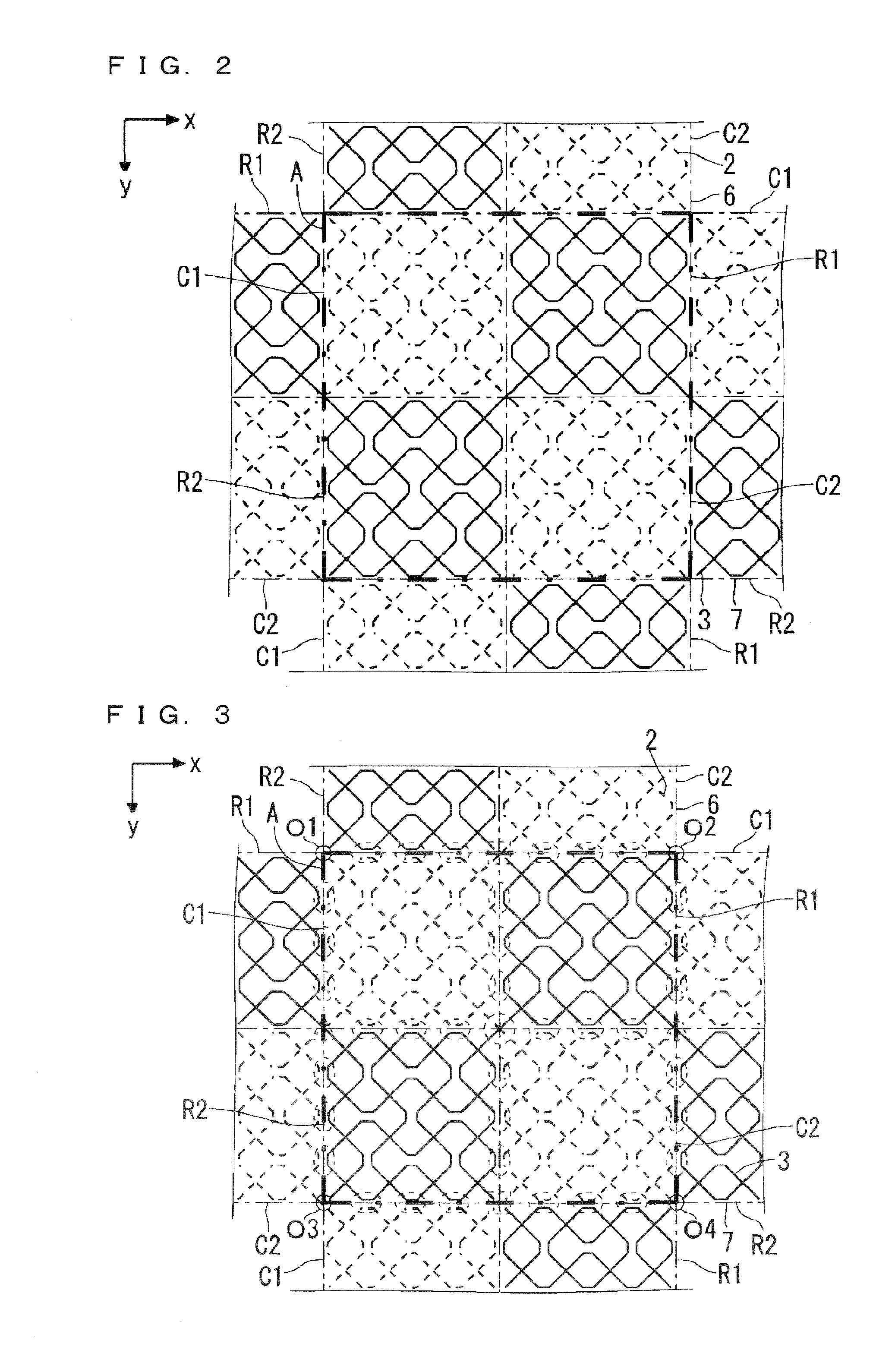
[0107]FIG. 15 is a diagram showing, on an enlarged scale, a region around the grid A in this preferred embodiment. Similarly to the preferred embodiment 1, a plurality of (here, four) block regions C1, C2, R1, and R2 each having a quadrangular shape are specified. The block regions C1, C2, R1, and R2 are obtained as a result of dividing the grid A. In each of the block regions C1 and C2 (first block region), only the detection column wires 2 are provided. In each of the block regions R1 and R2 (second block region), only the detection row wires 3 are provided. The block regions C1 and C2 in which the detection column wires 2 are provided and the block regions R1 and R2 in which the detection row wires 3 are provided are, as a who...

embodiment 3

Preferred Embodiment 3

[0136]In the preferred embodiments 1 and 2 described above, the detection column wire 2 provided in each of the block regions C1 and C2 that constitute the grid A includes two sets of the first and second zigzag wires 2a and 2b, and the detection row wire 3 provided in each of the block regions R1 and R2 that constitute the grid A includes two sets of the fifth and sixth zigzag wires 3a and 3b. However, the number of the sets of these zigzag wires included in each block region is not limited to two. Three or more sets may be provided. Therefore, in this preferred embodiment, a configuration will be described in which the number of sets of zigzag wires is an odd number (here, three).

[0137]FIG. 25 is a diagram showing, on an enlarged scale, a region around the grid A in this preferred embodiment. Here, similarly to the preferred embodiments 1 and 2, a plurality of (here, four) block regions C1, C2, R1, and R2 each having a quadrangular shape and obtained as a res...


PUM


Abstract

In a touch screen, the number of dummy column block region patterns is made smaller than the number of plurality of detection block region patterns. The plurality of detection block region pattern are obtained as a result of dividing a crossing region where a column direction wire bunch and a row direction wire bunch cross each other. The dummy column block region patterns are obtained as a result of dividing a crossing region where a dummy column direction wire bunch and a row direction wire bunch cross each other.

Description

BACKGROUND OF THE INVENTION[0001]1. Field of the Invention[0002]The present invention relates a touch screen, a touch panel, and a display device including them.[0003]2. Description of the Background Art[0004]Conventionally, a touch panel that detects a touch made with an indicator such as a finger and identifies the position coordinates of the touch is attracting attention as one of excellent interface means. For this touch panel, various types including resistive types and capacitive types have been proposed and put into practice as commercial products.[0005]As one kind of such capacitive type touch panels, a projected capacitive type touch panel is known, as disclosed in National Publication of Translation No. 9-511086 (1997). In this projected capacitive type touch panel, even when a front surface side of a touch screen having a touch sensor built therein is covered with a protection plate such as a glass plate having a thickness of about several mm, a touch to the protection pl...

Claims


Application Information

Patent Timeline
Patent Type & Authority Applications(United States)
IPC IPC(8): G06F3/044
CPCG06F2203/04111G06F3/044G06F3/0445G06F3/0446G06F3/0448
Inventor IMAMURA, TAKUJINAKAMURA, TATSUYAMORI, SEIICHIROMIYAYAMA, TAKASHIAGARI, MASAFUMINAKAGAWA, NAOKIONO, TAKESHI
Owner TRIVALE TECH LLC
Why Eureka
Try Eureka