
Pixel Circuit, Method of Driving the Same, and Organic Light Emitting Display Device Having the Same

a technology of organic light emitting display device and pixel circuit, which is applied in the field of display device, can solve the problems of insufficient threshold voltage compensation and non-uniform luminance of pixel circuit, and achieve the effect of improving contrast ratio, high speed and preventing non-uniform luminance due to hysteresis characteristics of driving transistors

Active Publication Date: 2013-08-01
SAMSUNG DISPLAY CO LTD
View PDF3 Cites 48 Cited by
  • Summary
  • Abstract
  • Description
  • Claims
  • Application Information

AI Technical Summary

Benefits of technology

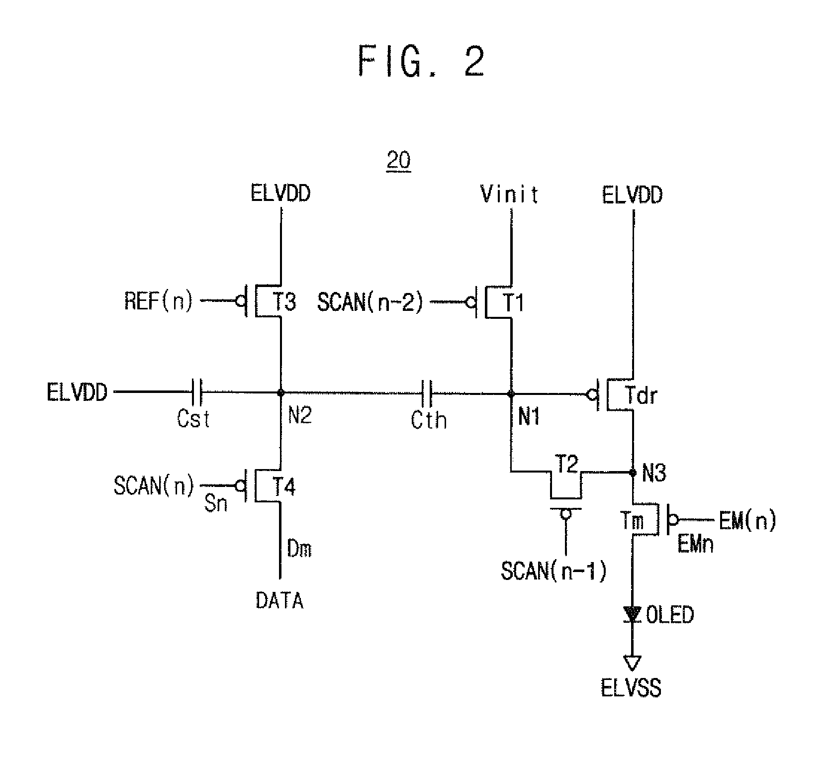
The present invention provides a pixel circuit that can prevent non-uniform luminance due to hysteresis characteristics of driving transistors. It achieves this by separately performing a threshold voltage compensating operation and a data programming operation for the driving transistors, and by applying the same initial value to gate electrodes of the driving transistors prior to the data programming operation. This results in improved luminance uniformity and a faster data programming operation. The pixel circuit can also obtain a sufficient threshold voltage compensation time period regardless of a data programming time period, and prevent non-uniform luminance due to hysteresis characteristics of driving transistors. Overall, this technology enhances the display quality of OLED devices.

Problems solved by technology

As a result, a non-uniform luminance may be caused among the pixel circuits, even when the same data voltage is applied to the pixel circuits.
However, threshold voltage compensation may be insufficiently achieved within a short data programming time period if a data programming operation and a threshold voltage compensating operation for the driving transistors are performed at the same time.

Method used


Image

  • Pixel Circuit, Method of Driving the Same, and Organic Light Emitting Display Device Having the Same
  • Pixel Circuit, Method of Driving the Same, and Organic Light Emitting Display Device Having the Same
  • Pixel Circuit, Method of Driving the Same, and Organic Light Emitting Display Device Having the Same

Examples


Embodiment Construction

[0043]Various example embodiments will be described more fully hereinafter with reference to the accompanying drawings, in which some example embodiments are shown. The present inventive concept may, however, be embodied in many different forms and should not be construed as limited to the example embodiments set forth herein. Rather, these example embodiments are provided so that this disclosure will be thorough and complete, and will fully convey the scope of the present invention to those skilled in the art. In the drawings, the sizes and relative sizes of layers and regions may be exaggerated for clarity. Like numerals refer to like elements throughout.

[0044]It will be understood that, although the terms first, second, third etc. may be used herein to describe various elements, these elements should not be limited by these terms. These terms are used to distinguish one element from another. Thus, a first element discussed below could be termed a second element without departing ...


PUM


Abstract

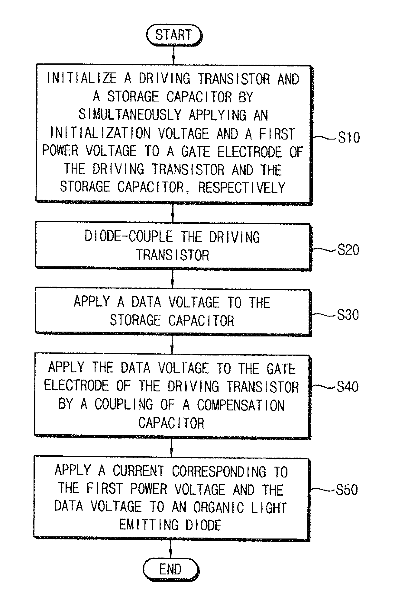
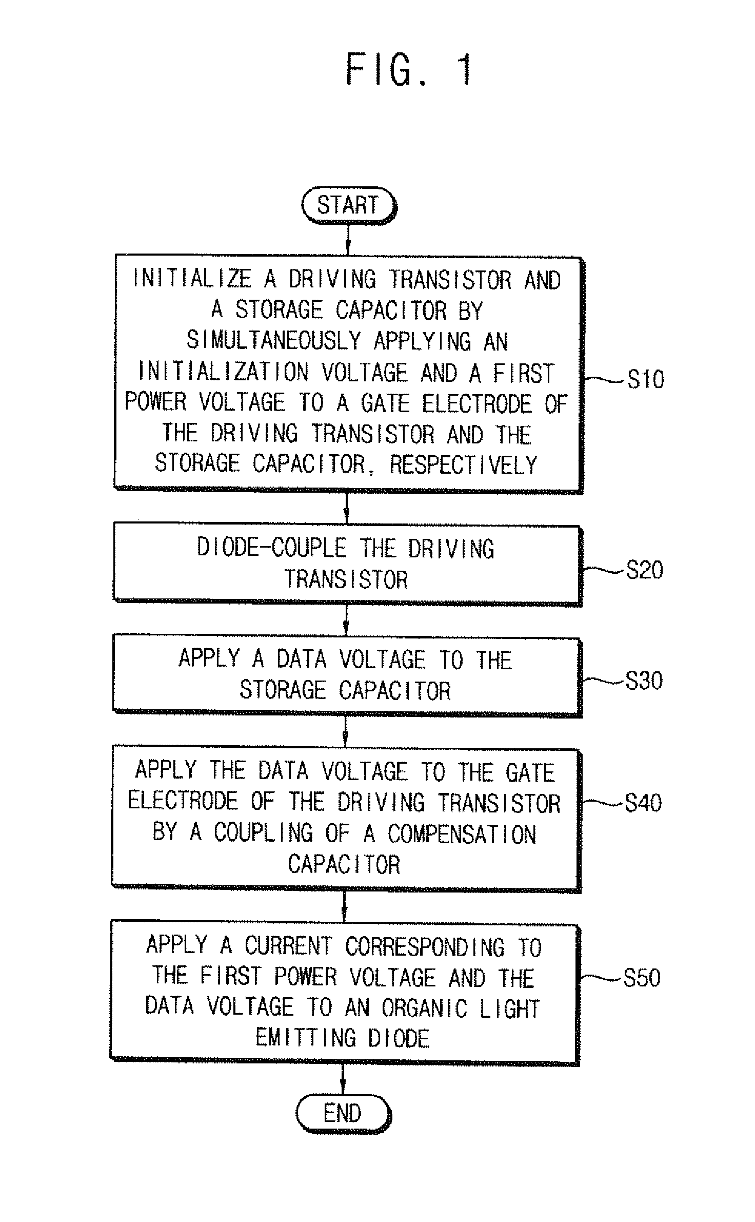
A method of driving a pixel circuit includes initializing a driving transistor and a storage capacitor by simultaneously applying an initialization voltage and a first power voltage to a gate electrode of the driving transistor and the storage capacitor, respectively, diode-coupling the driving transistor, applying a data voltage to the storage capacitor, applying the data voltage to the gate electrode of the driving transistor by a coupling of a compensation capacitor coupled between the gate electrode of the driving transistor and the storage capacitor, and applying a current corresponding to the first power voltage and the data voltage to an organic light emitting diode that is coupled to the driving transistor.

Description

CLAIM OF PRIORITY[0001]This application makes reference to, incorporates the same herein, and claims all benefits accruing under 35 U.S.C. §119 from an application earlier filed in the Korean Intellectual Property Office on the 27 Jan. 2012 and there duly assigned Serial No. 10-2012-0008159.BACKGROUND OF THE INVENTION[0002]1. Field of the Invention[0003]The present invention relates generally to a display device. More particularly, the invention relates to a pixel circuit, a method of driving the pixel circuit, and an organic light emitting display device having the pixel circuit.[0004]2. Description of the Related Art[0005]An organic light emitting display (OLED) device includes a plurality of scan-lines, a plurality of data-lines, and a plurality of pixel circuits that are arranged in a matrix form at crossing points of the scan-lines and the data-lines. Each pixel circuit includes a driving transistor that controls a current flowing through an organic light emitting diode.[0006]H...

Claims


Application Information

Patent Timeline
IPC IPC(8): G09G3/32G09G5/00
CPCG09G3/3233G09G3/3659G09G2300/0819G09G2320/045G09G2300/0861G09G2310/0251G09G2300/0852G09G3/30
Inventor KIM, TAE-JIN
Owner SAMSUNG DISPLAY CO LTD
Learn More