Intraocular lens implant

a technology of lens implant and lens shell, which is applied in the field of intraocular lens implant, can solve the problems of difficult selection of lens implant materials, unsuitable shape of such lens implant, and inability to adapt to the two variants above, so as to prevent corrosion and clouding, and improve sustainability

Inactive Publication Date: 2013-08-01
HAEFLIGER EDUARD ANTON
View PDF5 Cites 13 Cited by
  • Summary
  • Abstract
  • Description
  • Claims
  • Application Information

AI Technical Summary

Benefits of technology

[0011]Such lens implant is designed to reflect properties of the natural lens and its actuation mechanism as much as possible and respects the physiology of the eye. First, the lens implant although being designed by several components comprising two or more viewing elements and a spring element between the viewing elements is designed to—absent any external forces—take a flattened shape, which shape represents the shape of a natural lens enabling distant vision, i.e. what also sometimes is referred to as the lens being in an unaccommodated state. This shape reflects the shape of the natural lens and as such serves best for any accommodation processes as well as for any other physiological processes.
[0015]In a design step, the spring constant of the spring element of the lens implant is dimensioned such that a force produced by the lens capsule transforms the spring element from its relaxed state into a stretched state, i.e. pulls the spring element. The direction of transition is determined by means of the action direction of the spring element which typically is the optical axis of the lens implant. In a very advantageous embodiment, the spring constant is not only dimensioned such that it enables the lens capsule to stretch the spring element and by this enlarges the distance between the viewing elements along the optical axis, but is dimensioned such that the lens capsule is enabled to separate the viewing elements up to a distance which represents a state for near vision. The transition shall preferably be effected solely by means of tensions in the lens capsule.
[0016]It is believed that the present lens although comprising two spaced apart viewing elements may be closely aligned to the shape and the dimension of the natural lens mass and the lens implant as well as its actuation may be conform to the natural lens and its actuation. With the actuation being the same as with the natural lens, i.e. in particular without the ciliary muscle directly acting on the lens implant, a lens implanted person is not needed to experience, learn and adapt a different way of actuation / accommodation whereas a direct engagement of the ciliary muscle with a clamp of the lens implant may be irritating. In addition, it is believed that whenever the lens mass can be replicated into the synthetic lens implant at its best in shape and dimension, the basement membrane forming the lens capsule will likely better engage with the lens implant for the reason of a better fit and which may better prevent from corrosion and clouding. It is believed that the subcapsular epithelium from which the basement membrane is built will show a better sustainability when engaged with an aligned lens implant which follows the natural lens in the shape and actuation.

Problems solved by technology

Besides the requirement for adapting such lens implant according to the individual needs e.g. to a specific refraction index, the materials to manufacture such lens implant from are difficult to elect in view of the diverging needs of the lens implant being accommodatable on the one hand and persistent and long-living on the other hand.
Both variants above are not believed to be ideal in terms of adaptability of a lens implant to its natural environment.
However, the actuation of such lens implant as well as the shape of such lens implant is not considered to be a best fit in terms of adaptability of such lens implant to its environment.

Method used


Image

  • Intraocular lens implant
  • Intraocular lens implant
  • Intraocular lens implant

Examples


Embodiment Construction

[0028]Similar or relating components in the several figures may be provided with the same reference numerals.

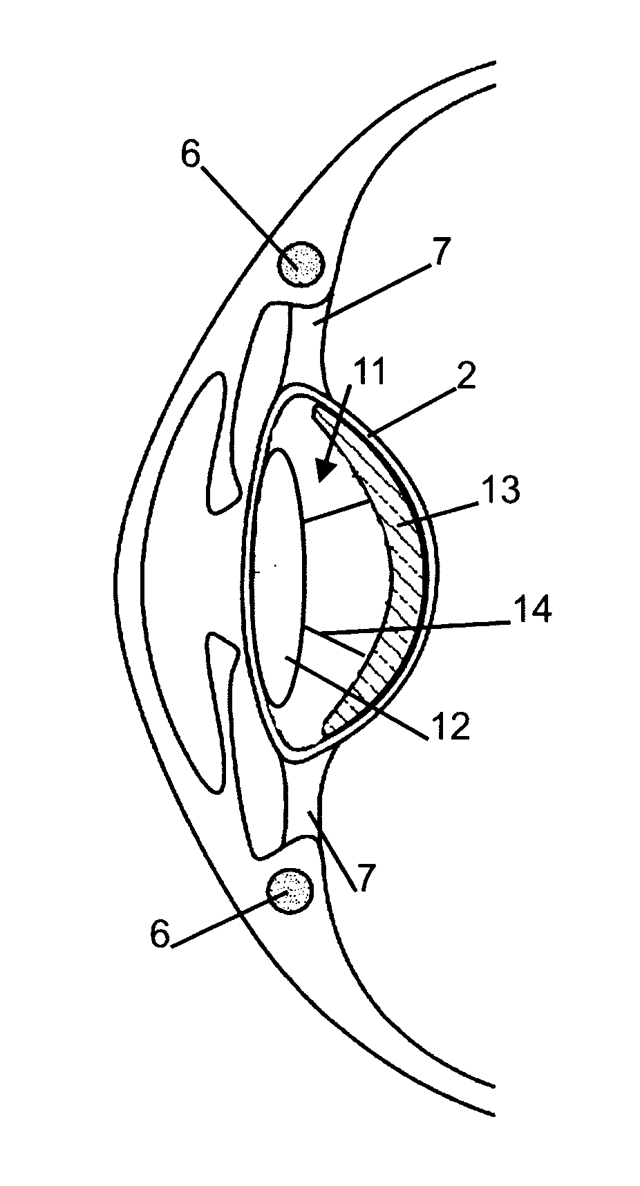
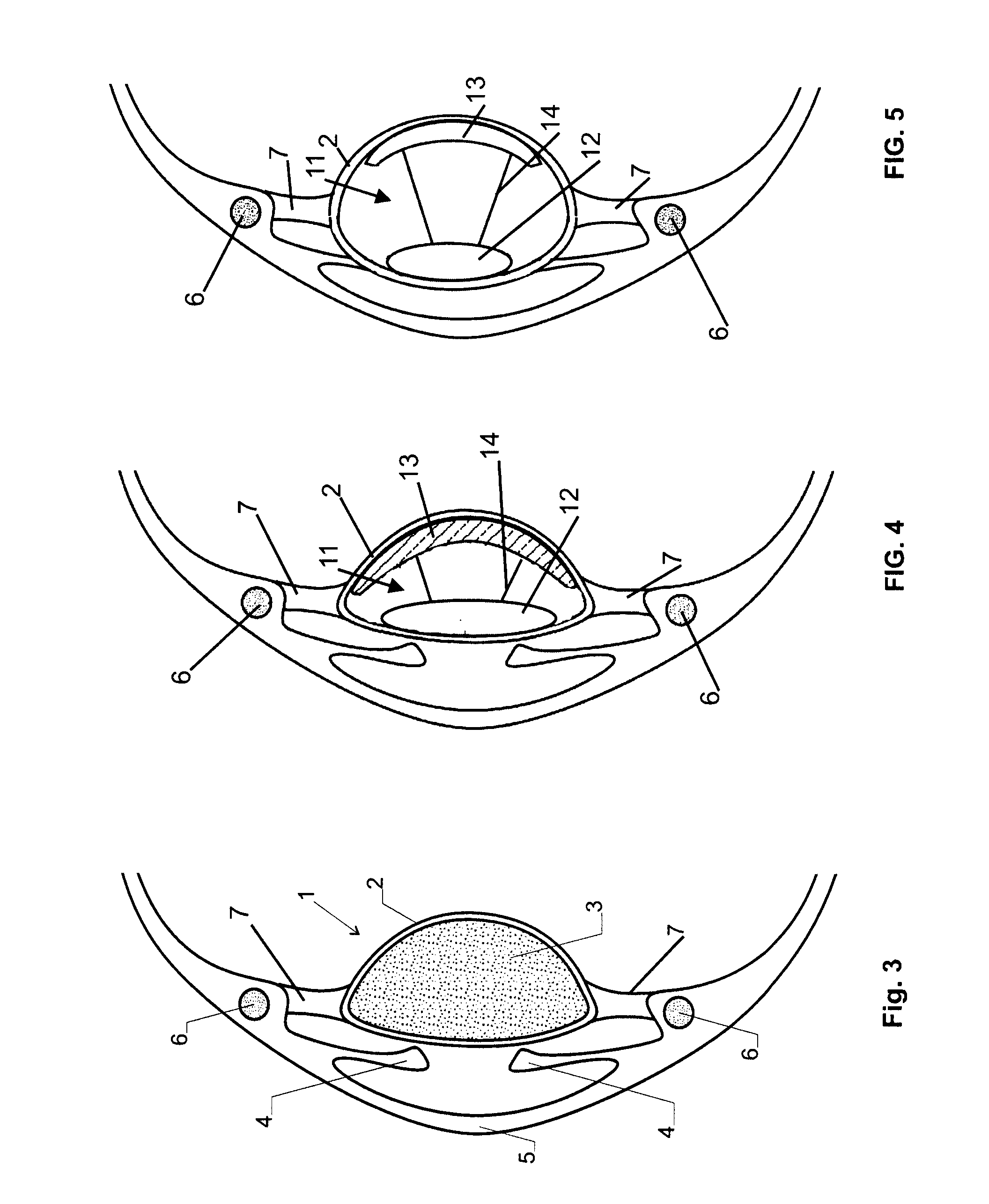
[0029]In FIG. 3 it is referred to a simplified cross section of a front part of the human eye which comprises a cornea 5, an iris 4 and a lens 1 comprising a lens mass 3 arranged in a lens capsule 2. The lens 1 is connected via zonule fibres 7 to a ciliary muscle 6. The ciliary muscle 6 takes the form of a ring that may contract and relax. A contraction of the ciliary muscle6 shall lead to accommodation which is understood as the eye focusing to an object in the near vision. Relaxation of the ciliary muscle 6 shall lead to a less accommodated state also referred to as unaccommodated state in which the eye is prepared for distant vision.

[0030]In a state in which the lens 1 is adapted for distant vision, the ciliary muscle 6 is relaxed as shown in FIG. 3. In such state the zonule fibres 7 are tense and pull the edge of the lens capsule 2 radially outwards such that the lens 1 t...


PUM


Abstract

An intraocular lens implant comprises two viewing elements (12, 13) and a spring element (14) in between. A distance between the first and the second viewing element (12, 13) along an optical axis (A-A′) of the lens implant (11) can be varied for adjusting the focal length of the lens implant (11). The lens implant (11) is designed to take a shape suitable for distant vision when the spring element (14) is in its relaxed state. A spring constant of the spring element (14) is dimensioned such that a force produced by a lens capsule (2) of the eye for holding the lens implant (11) transforms the spring element (14) from its relaxed state into a stretched state. By such design, the lens implant (11) may follow the same actuation principles as the natural lens does.

Description

TECHNICAL FIELD[0001]The invention relates to an intraocular lens implant, a method for manufacturing an intraocular lens implant, and a kit for manufacturing an intraocular lens implant.BACKGROUND ART[0002]Replacing the lens of a human eye by means of an intraocular lens implant may be indicated when due to aging processes the natural lens hardens and accommodation may no longer be achievable. For quite a while lens implants allowing accommodation include a replacement of the natural lens mass of the human eye by means of a synthetic lens mass. Besides the requirement for adapting such lens implant according to the individual needs e.g. to a specific refraction index, the materials to manufacture such lens implant from are difficult to elect in view of the diverging needs of the lens implant being accommodatable on the one hand and persistent and long-living on the other hand.[0003]Recently, it was proposed to replace a single body lens implant by a lens implant with two viewing el...

Claims


Application Information

Patent Timeline
Patent Type & Authority Applications(United States)
IPC IPC(8): A61F2/16
CPCA61F2/1613A61F2/1648A61F2/1624A61F2/1629A61F2210/0014A61F2/14A61F2/16
Inventor HAEFLIGER, EDUARD ANTON
Owner HAEFLIGER EDUARD ANTON
Why Eureka
Try Eureka