Suspension device

a suspension device and suspension technology, applied in the direction of cycle equipment, instruments, transportation and packaging, etc., can solve the problems the inability to sufficiently suppress and the inability to achieve the initial steering roll sufficiently suppressed, so as to achieve the effect of increasing the damping force and effectively suppressing the roll of the vehicle body

Active Publication Date: 2013-08-01
KYB CORP
View PDF18 Cites 21 Cited by
  • Summary
  • Abstract
  • Description
  • Claims
  • Application Information

AI Technical Summary

Benefits of technology

[0010]According to the above aspect, by causing a damper to generate a damping force opposing a roll moment of a vehicle body in response to a steering speed of a steering wheel at an initial stage of steering, the damping force of the damper increases, following a roll, without delay. Thus, the roll of the vehicle body can be sufficiently suppressed.
[0011]The faster a steering angular velocity of the steering wheel, the larger the roll moment acting on the vehicle body B. Thus, by causing a damping force corresponding to this steering angular velocity to be generated, the roll of the vehicle body can be effectively suppressed.

Problems solved by technology

However, in the above suspension device, it is difficult to sufficiently suppress the roll of the vehicle body for the following reason.
Thus, in the above suspension device, it is difficult to increase the damping forces of the dampers with good responsiveness even if the proportional gain is adjusted based on the steering speed, with the result that the roll at the initial stage of steering cannot be sufficiently suppressed.
Thus, the roll of the vehicle body is not sufficiently suppressed and lateral swinging movements of the vehicle body are not solved, thereby ride quality of the vehicle deteriorates.

Method used


Image

  • Suspension device
  • Suspension device
  • Suspension device

Examples


Embodiment Construction

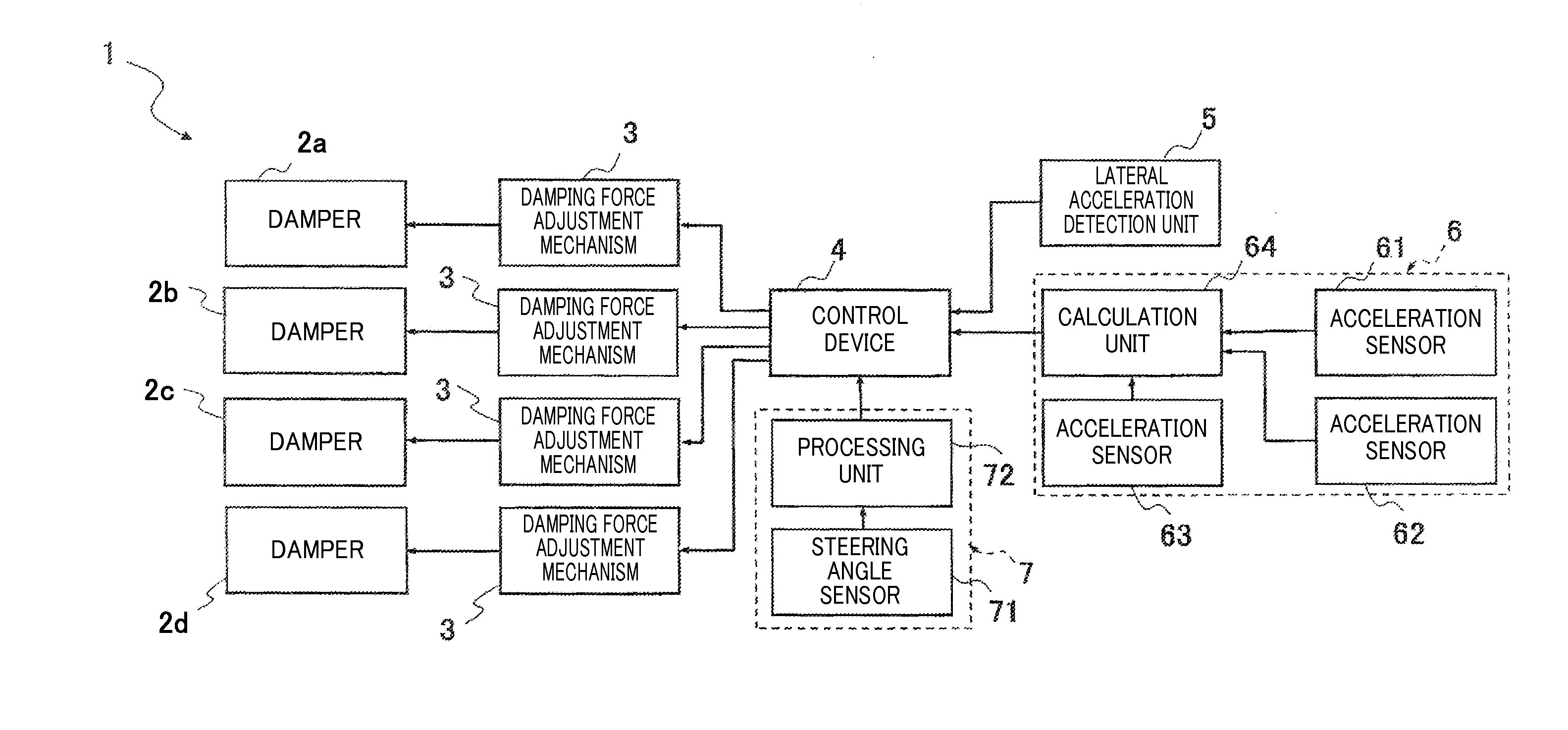
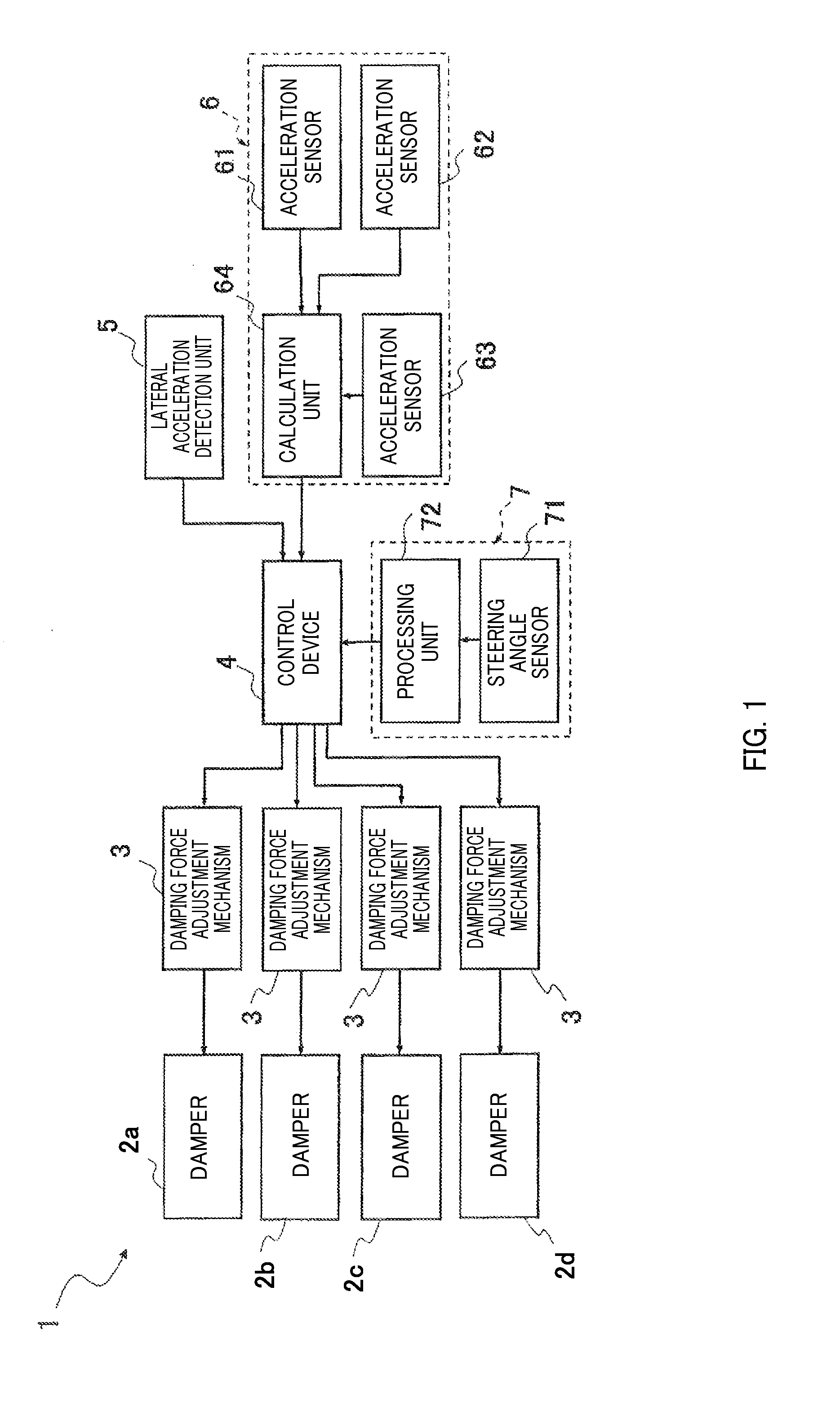
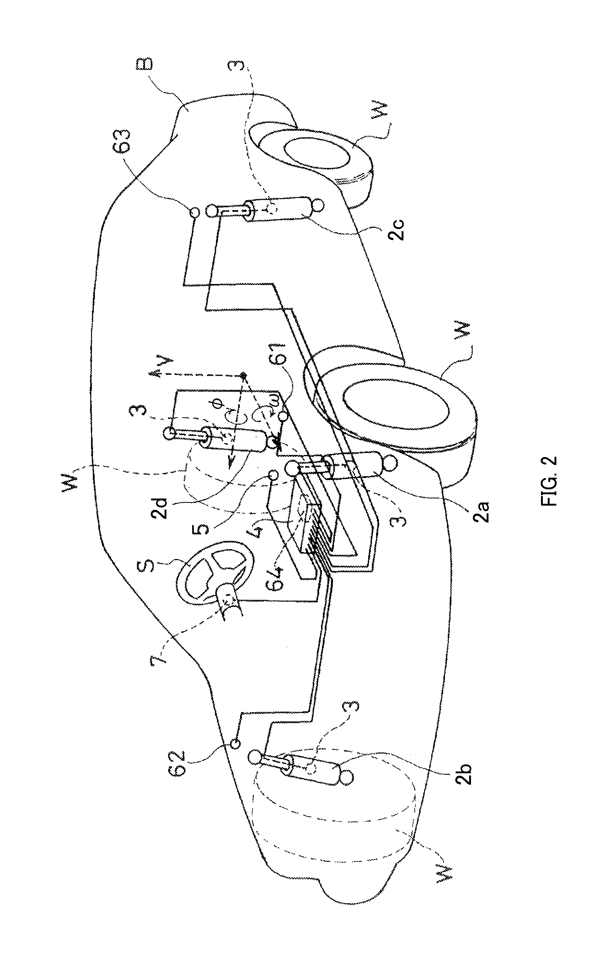
[0018]As shown in FIGS. 1 and 2, a suspension device 1 according to this embodiment includes dampers 2a, 2b, 2c and 2d, damping force adjustment mechanisms 3, a control device 4, a lateral acceleration detection unit 5, a roll angular velocity detection unit 6 and a steering angular velocity detection unit 7.

[0019]The dampers 2a, 2b, 2c and 2d are interposed between a vehicle body B and wheels W of a vehicle and suppress relative movements of the vehicle body and the wheels in a vertical direction. The damping force adjustment mechanisms 3 can adjust damping forces in the dampers 2n (n=a, b, c, d; the same applies hereinafter). The control device 4 controls these damping force adjustment mechanisms 3. The lateral acceleration detection unit 5 detects an acceleration in a vehicle lateral direction acting on the vehicle body. The roll angular velocity detection unit 6 detects a roll angular velocity of the vehicle body. The steering angular velocity detection unit 7 detects a steering...


PUM


Abstract

A suspension device includes damper interposed between vehicle body and wheel in vehicle and exerted damping force for suppressing vertical movements of vehicle body and wheel, damping force adjustment mechanism adjusts damping force, control device controls damping force adjustment mechanism, lateral acceleration detection unit detects an lateral acceleration acting on vehicle body, roll angular velocity detection unit detects roll angular velocity of vehicle body, and steering angular velocity detection unit detects steering angular velocity of steering wheel. The control device sets maximum damping force out of damping force calculated from steering angular velocity, damping force calculated from lateral acceleration and damping force calculated from roll angular velocity as steering initial stage additional damping force, calculates final damping force of damper using steering initial stage additional damping force and performs steering initial stage control of controlling damper when steering angular velocity exceeds predetermined dead band.

Description

TECHNICAL FIELD[0001]The present invention relates to a suspension device.BACKGROUND ART[0002]JP1994-48147A discloses a suspension device. This suspension device includes dampers interposed between a body and wheels of a vehicle, actuators for adjusting damping forces generated by the dampers, a control device for controlling the actuators to control the damping forces generated by the dampers, spring upper acceleration sensors for detecting accelerations of spring upper members in a vertical direction, and a steering sensor for detecting a steering angle of a steering wheel.[0003]This suspension device obtains a vertical speed of the spring upper member by integrating a vertical acceleration and calculates a bounce velocity, a pitching rate and a roll rate of the spring upper member. The suspension device also calculates a damping force to be generated by the damper by adding values obtained by multiplying these rates by proportional gains and causes the damper to generate the calc...

Claims


Application Information

Patent Timeline
Patent Type & Authority Applications(United States)
IPC IPC(8): B60G17/016
CPCB60G17/08B60G2400/102B60G17/0162B60G2400/41B60G2500/10B60G2400/104
Inventor OTAKE, TAKAFUMIHAGIDAIRA, SHINICHIMIYATANI, OSAMUOTA, YASUHIRO
Owner KYB CORP
Why Eureka
Try Eureka