Fluid Flow Control System

a flow control and flow control technology, applied in space heating and ventilation details, energy-efficient heating/cooling, domestic heating details, etc., can solve the problems of significant reduction or limitation of the operational effectiveness of the heat exchanger, and experience the reduction of the amount of useful heat that is recovered, so as to improve the control of the temperature

Active Publication Date: 2013-08-08
PATRICK GILBERT
View PDF17 Cites 9 Cited by
  • Summary
  • Abstract
  • Description
  • Claims
  • Application Information

AI Technical Summary

Benefits of technology

[0012]The invention therefore controls the flow within the supply and outlet paths of the heat exchanger by coordinating the operation of the first and second flow modulating devices. It will be noted that this stabilises the flow and allows the supply of at least some of the pre-heated fluid along the second flow path to the heating device. It is preferred that the fluid flow rates are substantially the same over a range of different flow rates corresponding substantially to the range of flow modulation provided by the modulating devices. Thus a consistently “balanced” flow rate may be maintained during use of the system.
[0013]The system may additionally be provided with a bypass flow path for providing the pre-heated fluid from the supply path to the use region, the bypass flow path being connected between the second flow path upstream of the heating device and the first flow path downstream of the heating device. A bypass flow modulating device is provided in this case, for controlling the flow of fluid in the bypass path. The bypass path enhances the control of the temperature and flow rate of the fluid delivered to the use region. The bypass path or bypass flow modulating device may also include a component / feature to generally resist the free flow of fluid therethrough or generally increase the fluid's loss of pressure head whilst flowing therethrough. It is preferred that the flow control device is further adapted to control the bypass flow modulating device such that the flow rate in the bypass path is a function of the flow rate in the first and / or second flow paths.

Problems solved by technology

Heat recovering shower installations that share the hot water supply with other hot water facilities typically transfer the recovered heat only to the shower's cold water supply which significantly reduces or limits the operational effectiveness of the heat exchanger.
Shower installations using heated water from heated water utilities that are not exclusive or dedicated (i.e. that can supply heated water simultaneously to additional separate hot water taps or outlets) with heat exchange devices (HXDs) according to the prior art are affected by unbalanced fluctuations in or disturbances to the balanced flow of heat mediating fluids through the heat exchange devices and consequently they experience reductions in the amount of useful heat that is recovered.

Method used


Image

  • Fluid Flow Control System
  • Fluid Flow Control System
  • Fluid Flow Control System

Examples


Embodiment Construction

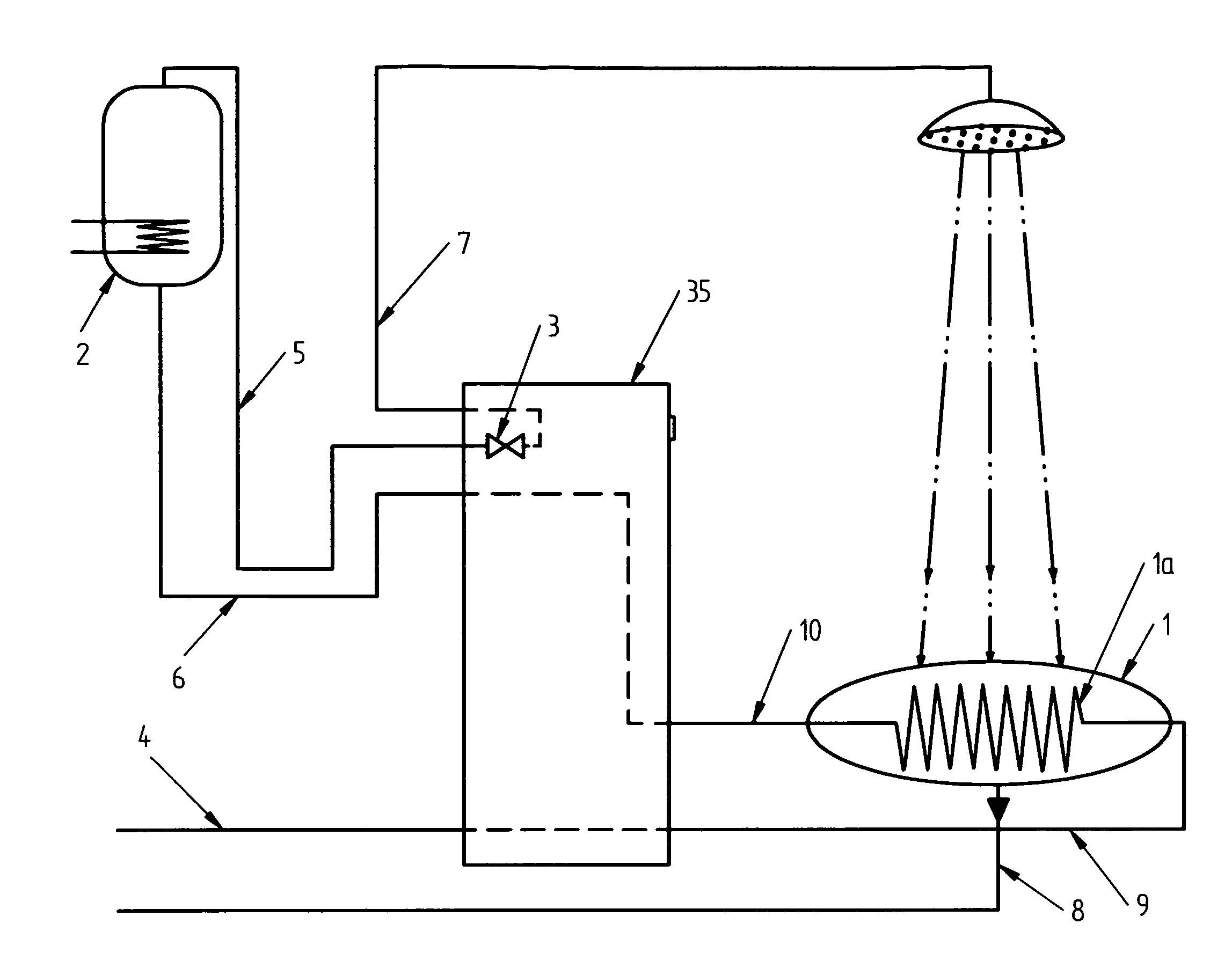
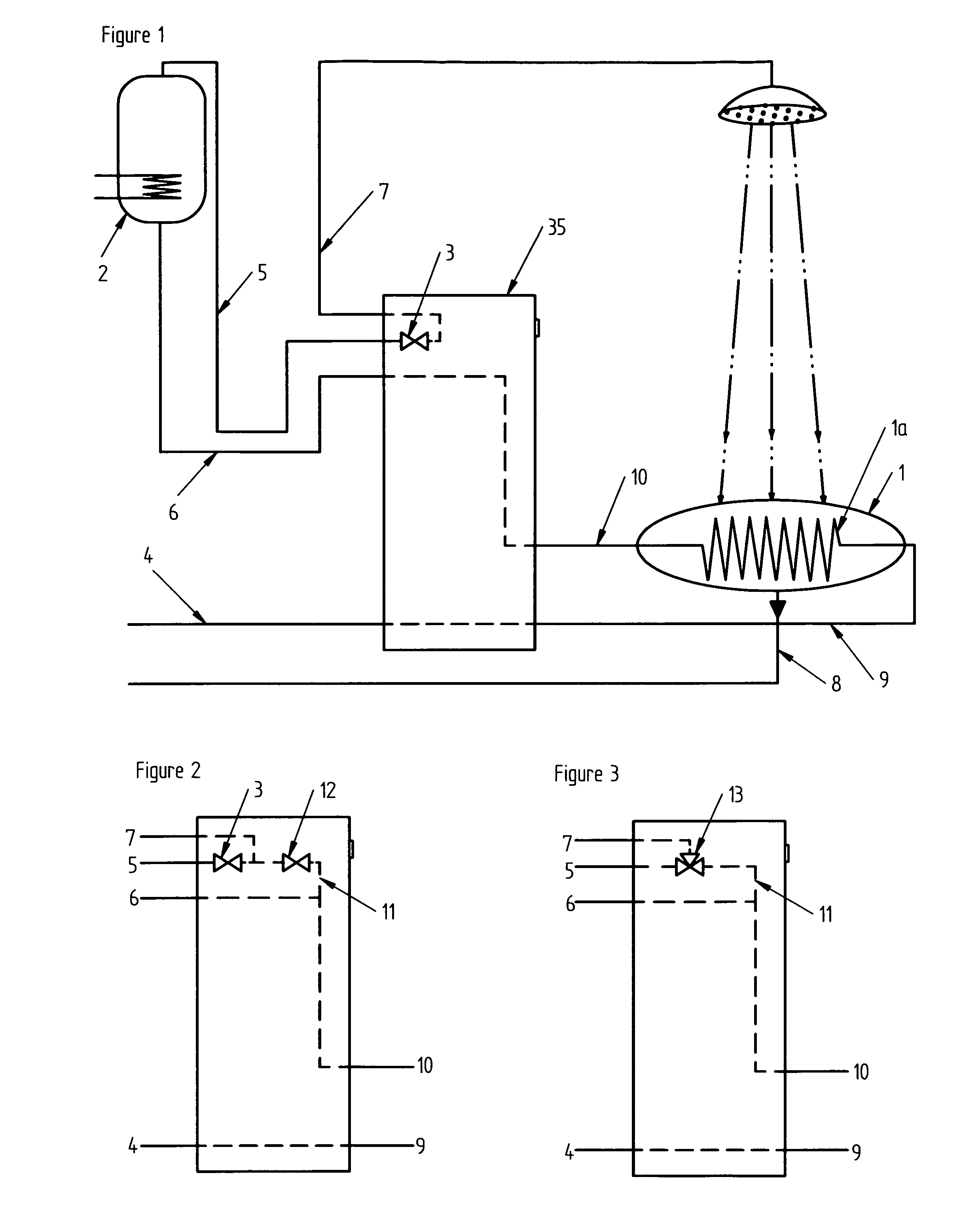
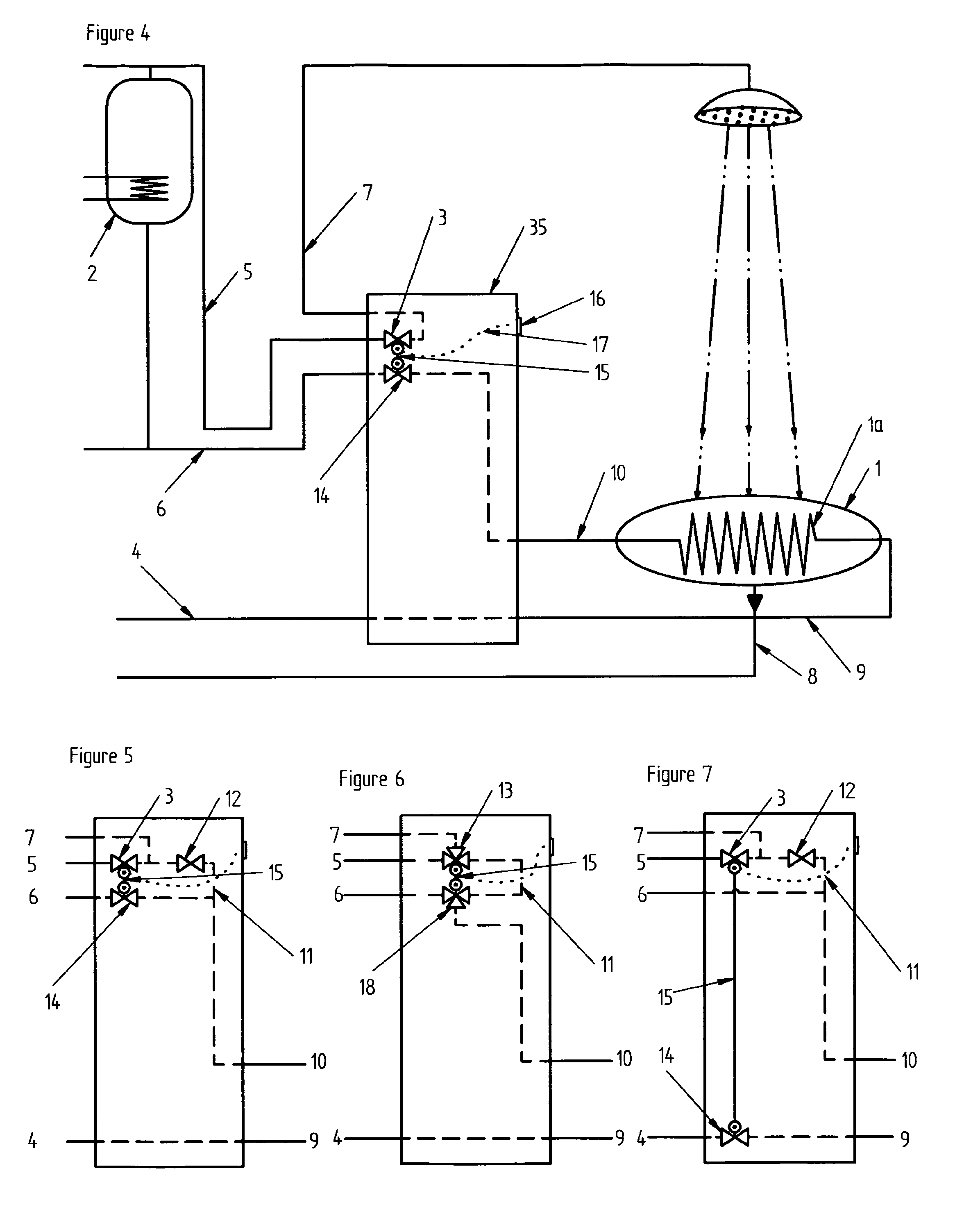
[0062]We firstly briefly describe a number of prior art shower installations in association with FIGS. 1 to 3. FIGS. 1 to 3 illustrate shower installations utilising a counterflow heat exchanger and a dedicated water heating unit according to the prior art, which typically have (with associated reference numerals):

[0063]A counterflow heat exchanger, with a thermally conductive serpentine conduit (1a);

[0064]A thermal accumulator with / or a water heating apparatus;

[0065]A valve or component for regulating the flow of heated water through the shower head. This may be associated with a valve or component to control the flow of unheated (or preheated) water through the shower head (12; FIG. 2) or combined with one as a 3-way mixer valve (13; FIG. 3), and are externally connected via four water flow conduits:

[0066]To receive a supply of fresh cold water (from external water mains);

[0067]To receive a supply of heated water (from a central hot water or water heating unit);

[0068]To deliver a ...


PUM


Abstract

A fluid flow control system has a heating device for heating a fluid and a first flow path for providing the heated fluid from the heating device to a use region. A heat exchanger has a supply path that received fluid from a fluid supply, and an outlet path that receives fluid from the use region, whereby the fluid in the supply path is pre-heated by the fluid in the outlet path. A second flow path provides pre-heated fluid from the supply path of the heat exchanger to the heating device. Modulating devices control fluid flow through the outlet path along the supply path. A flow control device controls the modulating devices such that the fluid flow rates in the fluid supply path and outlet path of the heat exchanger are balanced, so as to be substantially the same.

Description

FIELD OF THE INVENTION[0001]The present invention relates to a fluid flow control system. It also relates to valve mechanisms, plumbing components or accessories and their arrangement or combination in devices for balancing and stabilising the flow rates of fluid flows in two or more conduits, primarily for the application of enhancing the efficient recovery of heat through countercurrent heat exchange devices such as may be used in sanitary shower installations or other energy saving heated water utilities connected to multiple utility supplying water heating systems.[0002]Embodiments of this invention not only improve the effectiveness of heat recovery devices that save useful energy for example in the domestic / building environment but facilitate their general adoption by making their usage more practical and convenient, for the benefit of the environment and the conservation of its energy resources.BACKGROUND OF THE INVENTION[0003]Heat exchangers used for recovery of heat from th...

Claims


Application Information

Patent Timeline
Patent Type & Authority Applications(United States)
IPC IPC(8): E03B1/00G05D16/10
CPCE03C1/0408E03C1/044E03C2001/005G05D16/103F24D19/1051F24D2200/20E03B1/00F24D17/001Y02B30/18Y10T137/7793Y10T137/6416F16K11/0445
Inventor GILBERT
Owner PATRICK GILBERT
Why Eureka
Try Eureka