Smart installation/processing systems, components, and methods of operating the same

Active Publication Date: 2013-08-08
FATIGUE TECH
View PDF8 Cites 16 Cited by
  • Summary
  • Abstract
  • Description
  • Claims
  • Application Information

AI Technical Summary

Benefits of technology

[0023]A dynamically controlled tool is a radical departure from the over 40 years of conventional cold working techniques. A dynamically controlled tool may advantageously reduce upset and/or eliminate axial flow of material. A dynamically controlled tool may advantageously produce more uniform stress around a hole, even proximate ridges caused by a multi-segment selectively expandable portion or member. Such may lead to improved fatigue life. A dynamically controlled tool may advantageously eliminate the use of disposable sleeves, thereby reducing the waste stream and operational costs. A dynamically controlled too

Problems solved by technology

Observation has made apparent that human operators often lack the attention, training or desire to correctly operate processing tools.
This variation

Method used


Image

  • Smart installation/processing systems, components, and methods of operating the same
  • Smart installation/processing systems, components, and methods of operating the same
  • Smart installation/processing systems, components, and methods of operating the same

Examples


Example

[0114]In the following description, certain specific details are set forth in order to provide a thorough understanding of various embodiments of the invention. However, one skilled in the art will understand that the invention may be practiced without these details.

[0115]Unless the context requires otherwise, throughout the specification and claims which follow, the word “comprise” and variations thereof, such as, “comprises” and “comprising” are to be construed in an open, inclusive sense, that is as “including, but not limited to.”

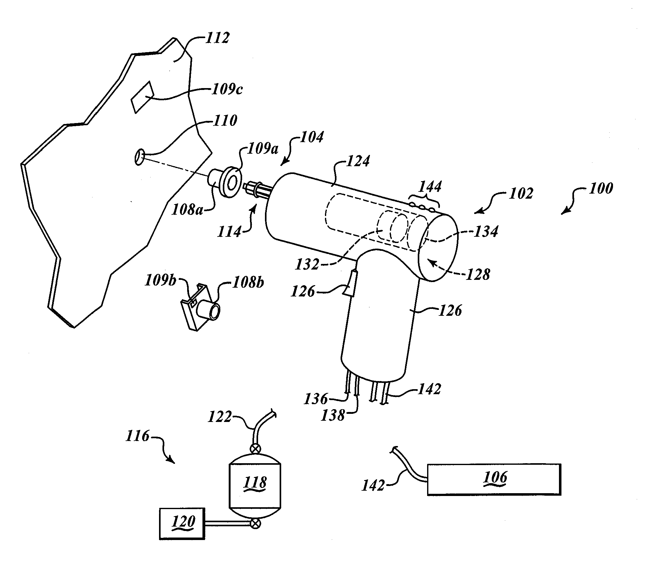
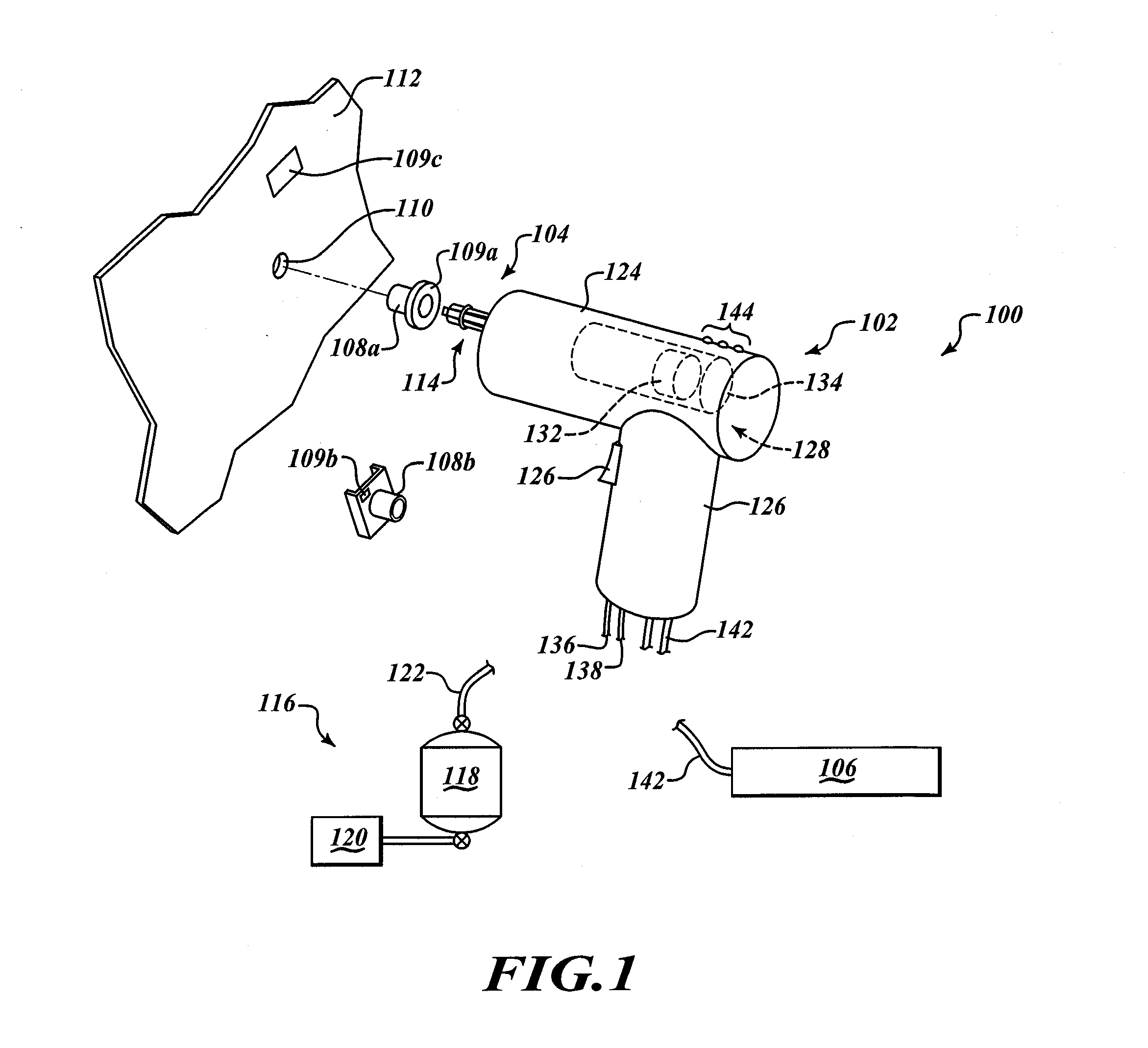
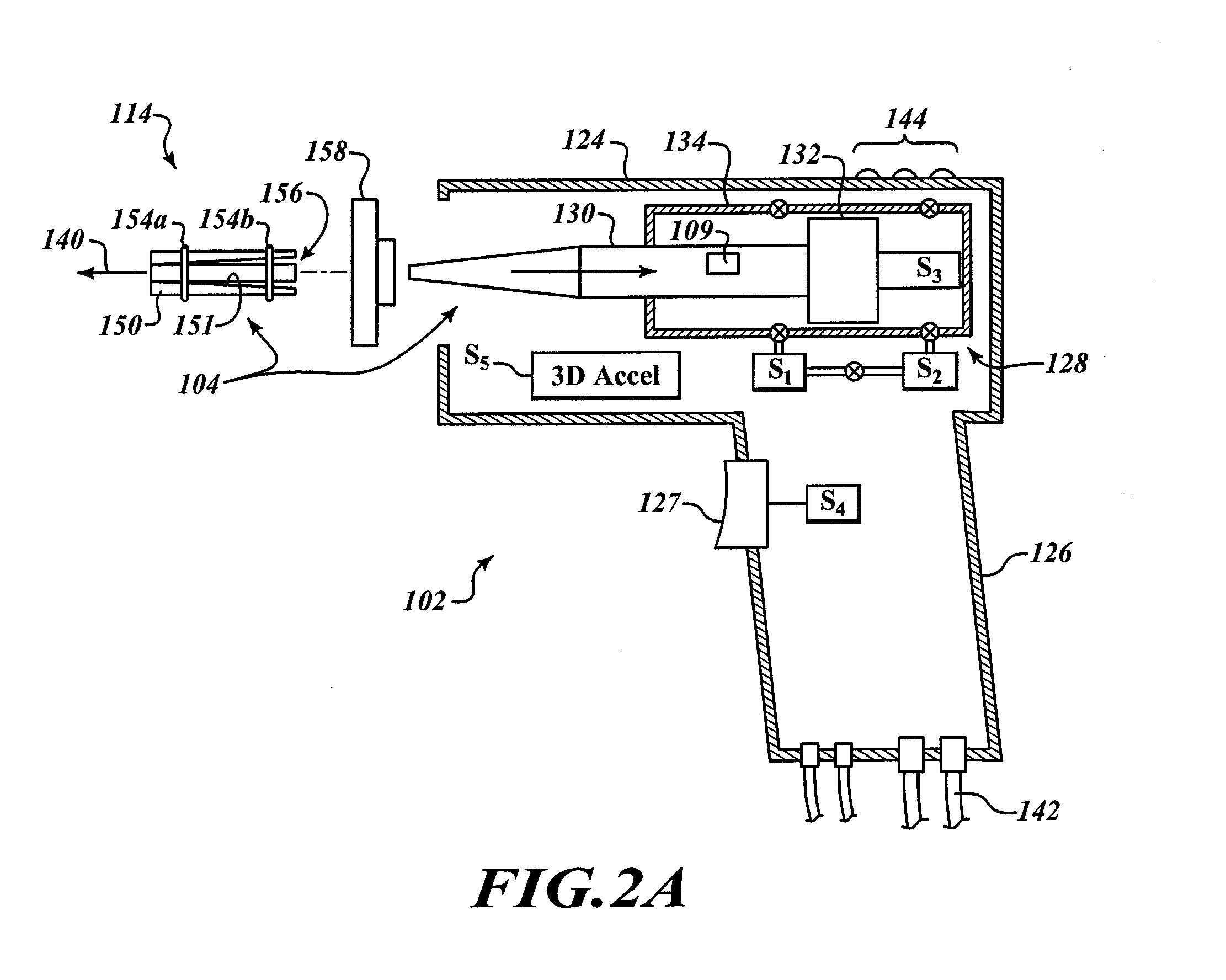
[0116]The headings provided herein are for convenience only and do not interpret the scope of meaning of the claimed invention. The following description relates to installation / processing systems used to install expandable members (e.g., tubular bushings, rivetless nut plates, grommets, fittings, sleeves, etc.) in openings, such as non-through holes in workpieces. The systems can also be used to process workpieces, such as cold working holes in workpie...


PUM

PropertyMeasurementUnit
Forceaaaaaaaaaa
Pressureaaaaaaaaaa
Sizeaaaaaaaaaa

Abstract

A processing system employs a processing tool to process workpieces, for example cold working holes and/or installing expandable members into holes. Sensors sense various aspects of the processing. Information regarding performance of the process and/or materials may be stored, for example a hole-by-hole or a workpiece-by-workpiece basis, allowing validation of processing. Information also allows dynamic operation of the processing tool. Analysis of response relationships (e.g., pressure or force versus position or distance) may provide insights into the process and materials, and/or facilitate the real-time feedback including control, alerts, ordering replacement for consumable components.

Description

BACKGROUND[0001]1. Field[0002]This disclosure generally relates to installation / processing systems for installing expandable members into holes in workpieces and / or cold expanding holes in workpieces.[0003]2. Description of the Related Art[0004]Conventional installation tools are used to install bushings in holes within workpieces. These installation tools often have an expansion mandrel with an enlarged tapered portion used to expand the bushing. To radially expand the bushing, the expansion mandrel is inserted into an opening in the bushing. The bushing and mandrel are simultaneously inserted into a hole in a workpiece. When the bushing is positioned in the hole of the workpiece, the enlarged tapered portion of the mandrel extends outwardly from the backside of the workpiece. These types of installation tools thus require an adequate amount of backside clearance and are unsuitable for installing bushings in non-through holes, blind holes, or other holes having limited backside cle...

Claims


Application Information

Patent Timeline
IPC IPC(8): B21D31/04B29C67/00
CPCB21D31/04B29C67/00B23P9/025G05B19/41815B23P11/005C21D7/02G01B13/10G05B19/00Y02P90/02
Inventor ROSS, JAMES RYUNOSHINJOHNSON, TIMOTHY HOWARDBAKKEN, DOUGDOOLEY, KEVIN J.
Owner FATIGUE TECH
Why Eureka
Try Eureka