Stator for rotary electric machine

a technology of rotary electric machines and rotors, which is applied in the direction of dynamo-electric components, ac commutators, dynamo-electric machines, etc., can solve the problems of high manufacturing cost, difficult downsizing, and large so as to reduce manufacturing costs and reduce the volume of coil end portions, the effect of reducing the size of the whole devi

Inactive Publication Date: 2013-08-08
HONDA MOTOR CO LTD
View PDF10 Cites 53 Cited by
  • Summary
  • Abstract
  • Description
  • Claims
  • Application Information

AI Technical Summary

Benefits of technology

[0007]The present invention has been developed addressing such problems, and an object of the invention is to provide a stator for a rotary electric machine, wherein reduction in the manufacturing cost and downsizing by reducing the volume of coil end portions can be attained for the stator.

Problems solved by technology

However, the stator disclosed by Patent Document 1 has a problem in that the cost is high because it is necessary to bend leads and forge leads in order to form the above-described U-shaped leads.
Further, the bent portions of the U-shaped leads of the stator presented by Patent Document 1 are extending along the rotation axis direction of a rotary electric machine, which causes a problem that the volume of the coil end portions is large and downsizing is not easy.

Method used


Image

  • Stator for rotary electric machine
  • Stator for rotary electric machine
  • Stator for rotary electric machine

Examples


Embodiment Construction

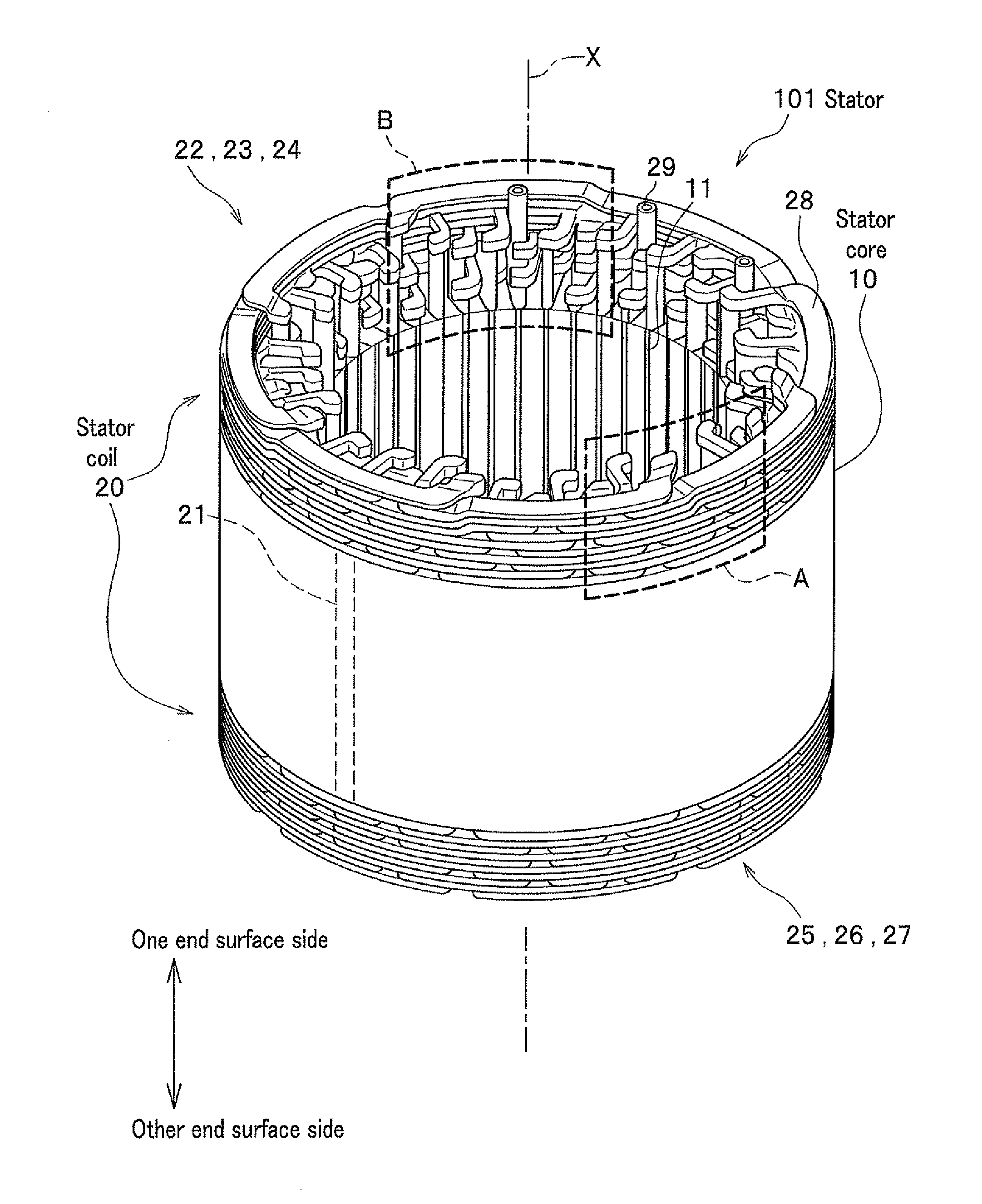
[0053]A preferred embodiment of a stator according to the present invention (hereinafter, referred to merely as stator) for a rotary electric machine will be described below, referring to FIGS. 1 to 13. Dimensions and scales of structures shown in respective figures may be exaggerated for the convenience of description.

[0054]A stator 101 is one for a rotary electric machine for rotational motion by conversion of electrical energy supplied from outside into mechanical energy. Electrical energy is input to the stator 101 from the outside, and the stator 101 generates a magnetic field for rotational motion of a rotor provided with permanent magnets. The stator 101 can be used, for example, as the stator of an induction motor, synchronous motor, or the like. As shown in FIG. 1, the stator 101 includes a stator core 10 and stator coils 20.

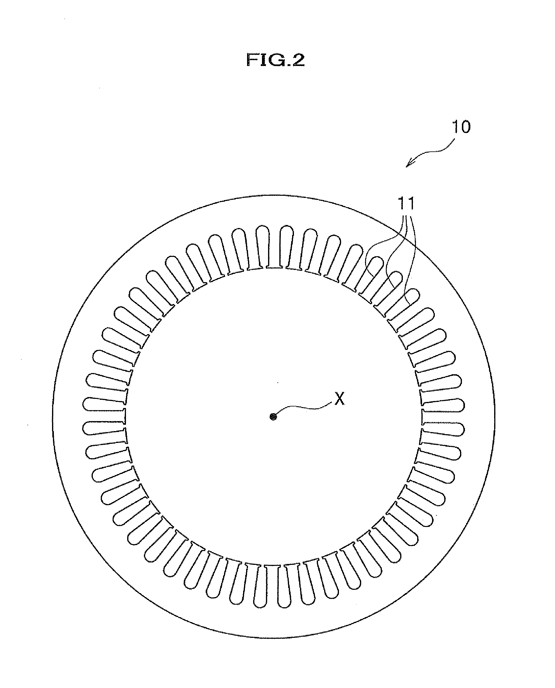
[0055]The stator core 10 is, as shown in FIG. 1, a core member to which the stator coils 20 are attached. The stator core 10 is, as shown in FIG. 2, fo...


PUM


Abstract

The manufacturing cost of a stator for a rotary electric machine can be reduced, and the volume of coil end portions can be reduced to enable downsizing. A stator for a rotary electric machine includes: a cylindrical stator core with plural slots formed at an inner circumferential surface; a plurality of coil segments received by the slots; a plurality of first coil end plates electrically connected with the coil segments on either one of end surfaces of the stator core; and a plurality of second coil end plates electrically connected with the coil segments on the other end surface of the stator core. The plate portion of at least one of the plurality of the first coil end plates is formed longer than the plate portions of the other first coil end plates and has a stepped portion.

Description

CROSS REFERENCE TO RELATED APPLICATION[0001]This application claims the foreign priority benefit under Title 35, United States Code, §119(a)-(d) of Japanese Patent Application No. 2012-025115, filed on Feb. 8, 2012 in the Japan Patent Office, the disclosure of which is herein incorporated by reference in its entirety.BACKGROUND OF THE INVENTION[0002]1. Field of the Invention[0003]The present invention relates to a stator used for a rotary electric machine including an electric motor and a generator.[0004]2. Description of the Related Art[0005]Conventionally, various structures have been presented for a stator, including a stator core, a stator coil for a rotary electric machine. For example, a stator is disclosed, in Patent Document 1 (Japanese Patent Application Laid-open No. 2008-148479 A, refer to FIG. 4), that includes s stator core having teeth, U-shaped leads inserted in the teeth, and bus bars connected with the U-shaped leads.[0006]However, the stator disclosed by Patent Doc...

Claims


Application Information

Patent Timeline
Patent Type & Authority Applications(United States)
IPC IPC(8): H02K3/12
CPCH02K3/12
Inventor OKIMITSU, TAKEOMI
Owner HONDA MOTOR CO LTD
Why Eureka
Try Eureka