Optical layered, polarizer, and image display device

a polarizer and optical layer technology, applied in the direction of polarising elements, instruments, non-linear optics, etc., can solve the problems of difficult to achieve a hardness of 4h in the pencil hardness test defined above, and the hard coat layer cannot be imparted sufficient hardness, etc., to achieve excellent hardness and abrasion resistance

Active Publication Date: 2013-08-08
DAI NIPPON PRINTING CO LTD
View PDF3 Cites 2 Cited by
  • Summary
  • Abstract
  • Description
  • Claims
  • Application Information

AI Technical Summary

Benefits of technology

[0101]Because the optical layered body of the present invention is configured as described above, the hard coat layer has excellent hardness and abrasion resistance. Thus, the optical layered body of the present invention is suitably applicable to c

Problems solved by technology

However, in the case of a hard coat film provided with a hard coat layer formed using such an ultraviolet-curable resin, it has been difficult to impart sufficient hardness to the hard coat layer (for example, a pencil hardness of 4H or more as measured by a test in accordance with a pencil hardness test specified in JIS K5600-5-4 (1999) at a load of 4.9 N).
Unfortunately, conventional hard coat films cannot fully respond to such a demand.
In the case of a hard coat film provided with a hard coa

Method used


Image

  • Optical layered, polarizer, and image display device
  • Optical layered, polarizer, and image display device

Examples


example 1

[0133]A triacetylcellulose substrate (thickness of 40 μm, produced by Konica Minolta Holdings, Inc.; KC4UYW) was provided, and a hard coat layer-forming composition 1 was applied to one side of the substrate. The thus-obtained coating film was dried in a thermal oven at 70° C. for 60 seconds to evaporate the solvent in the coating film, and irradiated with ultraviolet light to a cumulative amount of light of 100 mJ / cm2 to cure the coating film. Thereby, a hard coat layer of 10 g / cm2 (dry basis) was formed, and an optical layered body was prepared.

examples 2 to 10

, Comparative Examples 1 to 8, Reference Examples 1 to 3

[0134]Optical layered bodies of Examples 2 to 10, Comparative Examples 1 to 8, and Reference Examples 1 to 3 were prepared in the same manner as in Example 1, except that hard coat layer-forming compositions 2 to 21 were used as shown in Table 2 instead of the hard coat layer-forming composition 1.

[0135]The optical layered bodies obtained in Examples, Comparative Examples, and Reference Examples were evaluated by the following methods. Table 2 shows the results.

(Evaluation 1: Measurement of Martens Hardness)

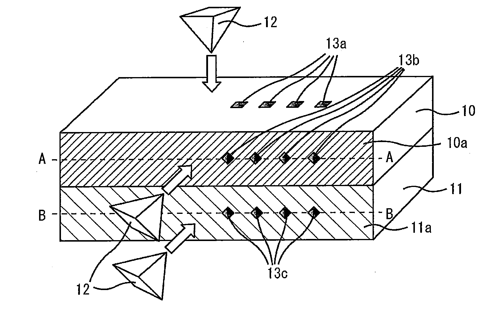
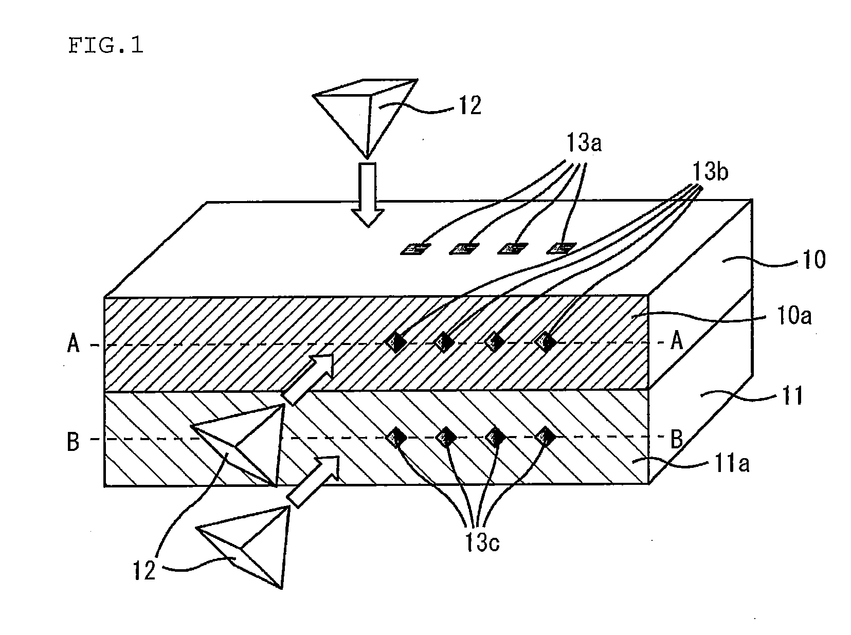
[0136]The optical layered bodies of Examples, Comparative Examples, and Reference Examples were subjected to measurement of Martens hardness by nanoindentation using Picodentor HM-500 produced by Fischer Instruments K.K. The measurement was performed on the surface of each hard coat layer, the center of the cross-section thereof, and the center of the cross-section of each triacetylcellulose substrate.

[0137]With an applied l...


PUM


Abstract

The present invention provides an optical layered body having excellent hardness, abrasion resistance, and flexibility.
The present invention provides an optical layered body having a hard coat layer on one side of a triacetylcellulose substrate, wherein a Martens hardness (N1) of a surface of the hard coat layer, a Martens hardness (N2) of the center of the cross-section of the hard coat layer, and a Martens hardness (N3) of the center of the cross-section of the triacetylcellulose substrate have a relationship of N2>N1>N3 as determined by nanoindentation, and the hard coat layer has a pencil hardness of 4H or more as measured by a test in accordance with a pencil hardness test defined in JIS K5600-5-4 (1999) at a load of 4.9 N.

Description

TECHNICAL FIELD[0001]The present invention relates to an optical layered body, a polarizer, and an image display device.BACKGROUND ART[0002]Image display devices such as cathode-ray tube (CRT) display devices, liquid crystal displays (LCDs), plasma display panels (PDPs), electroluminescence displays (ELDs), field emission displays (FEDs), touch panels, electronic paper, and tablet PCs are required to be provided with abrasion resistance in order to prevent damage during handling.[0003]In response to such request, a hard coat film having a hard coat (HC) layer on a substrate film, and a hard coat film provided with optical functions such as anti-reflection properties and anti-glare properties have been usually used to improve the abrasion resistance of the image display surfaces of these image display devices.[0004]As an example of hard coat films having a hard coat layer on a substrate film, Patent Literature 1 discloses a hard coat film, wherein a hard coat layer formed using an ul...

Claims


Application Information

Patent Timeline
IPC IPC(8): G02B1/10
CPCG02B5/30Y10T428/24983Y10T428/24421G02B1/105G02B1/14G02B5/3033G02F1/133528
Inventor INOMATA, YUYAHORIO, TOMOYUKINISHIZONO, TAKESHIYAMAMOTO, KANA
Owner DAI NIPPON PRINTING CO LTD
Why Eureka
Try Eureka