
Method and System for Measurement Report in Coordinated Multi-Point Transmission and Reception System

a multi-point transmission and reception system technology, applied in the field of mobile communication techniques, can solve the problems of very small improvement throughput, very complex execution, and overwhelming majority of companies bullish about comp technology, and achieve the effect of avoiding reporting measurement sets and reducing signaling overhead

Inactive Publication Date: 2013-08-08
ZTE CORP
View PDF14 Cites 9 Cited by
  • Summary
  • Abstract
  • Description
  • Claims
  • Application Information

AI Technical Summary

Benefits of technology

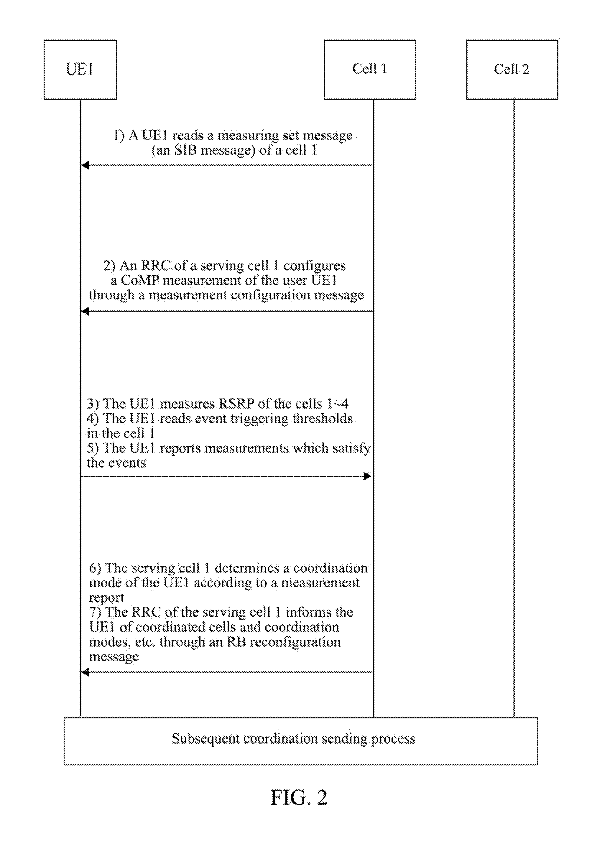
The present invention provides better performance by introducing a new event report triggering criterion, which reduces reporting frequency and signaling overhead. It also analyzes the movement situation of a user equipment (UE) at the cell edge to ensure enough residual time for the UE and reduces processing for users who quickly traverse the cell edge. These improvements result in improved performance and efficiency for wireless networks.

Problems solved by technology

Therefore, the overwhelming majority of companies are very bullish about the CoMP technology.
However, sharing the data / Channel State Information (CSI) between multiple eNBs needs extremely large backhaul capacity, and thus the execution is very complicated.
Therefore, an issue related to the CoMP is how to select a coordinated cell cluster, so as to reach the maximization of cell throughput on the acceptable scheduling complexity and backhaul capacity.
After the CoMP is used, the improvement of throughput is very tiny and information interaction is wasted.
Therefore, the following problems mainly exist in the related art.
1) Since most of CoMP users are located at cell edges, the number of users located at the handover positions account for about 5% and the number of users located at the CoMP account for about 30% according to the analysis, excessive signaling overhead is caused if all the users report measurement sets frequently.

Method used


Image

  • Method and System for Measurement Report in Coordinated Multi-Point Transmission and Reception System
  • Method and System for Measurement Report in Coordinated Multi-Point Transmission and Reception System
  • Method and System for Measurement Report in Coordinated Multi-Point Transmission and Reception System

Examples


application example 1

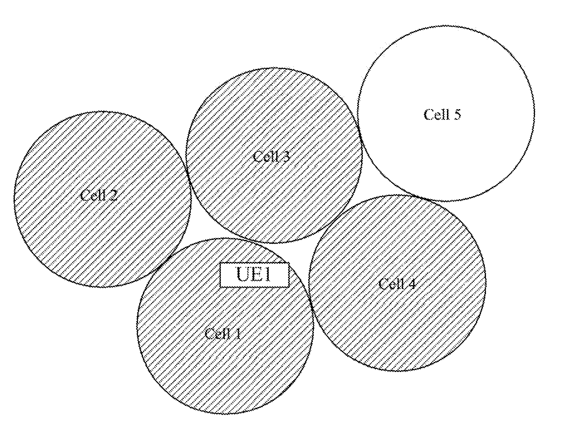
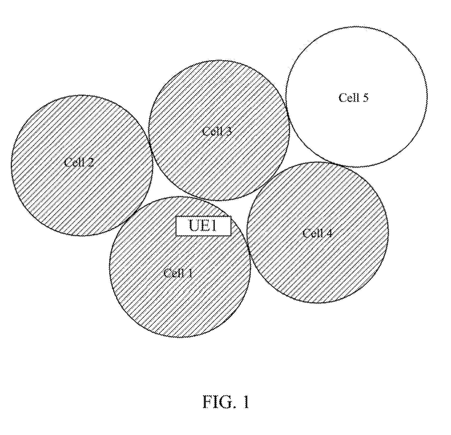
[0108]With reference to FIG. 3, in the example, according to the measurement configuration, a user UE1 completes measurements of RSRP and δRSRP of a cell set {cell 2, cell 3, cell 4}, and uses public pilot symbols of the cells 1˜4 respectively to perform measurement. It is assumed that the measurement values satisfy RSRP1>RSRP2>RSRP3>RSRP4, meanwhile, the UE1 calculates

SIR=RSRP1∑k=24RSRPk

and δRSRP,1 and compares the

SIR=RSRP1∑k=24RSRPk

and δRSRP,1 with the θ2 and θ1, once a report condition is satisfied, the UE1 reports a measurement report.

[0109]In the reported measurement report, the UE1 can report a serving cell and a cell with the strongest signal intensity in the signal intensity order. At the point, the cell 2 can be taken as a coordinated cell, and the position of the UE1 is as shown in FIG. 3.

application example 2

[0110]With reference to FIG. 4, in the example, a user UE1 completes measurements of cell RSRP and δRSRP of a cell set {cell 2, cell 3, cell 4} according to the measurement configuration, and if a signal intensity satisfies RSRP1>RSRP2>RSRP3>RSRP4, the UE1 calculates

SIR=RSRP1∑k=24RSRPk

and δRSRP,1 at the same time and compares the

SIR=RSRP1∑k=24RSRPk

and δRSRP,1 with the θ2 and θ1, once a report condition is satisfied, the UE1 reports a measurement report.

[0111]Alternatively, if a difference RSRP2-RSRP3 of signal intensities of two measuring cells with the strongest signal intensity is less than a certain value, the UE1 can report the cell 2 and cell 3 simultaneously. At the point, the cell 2 and cell 3 can be taken as coordinated cells simultaneously, and the position of the UE1 is as shown in FIG. 4.

[0112]It can be seen from the above description that, the threshold θ1 actually reflects the movement situation at the cell edge of the UE1, being less than the threshold θ1 ensures that ...


PUM


Abstract

A method and system for measurement reporting in a Coordinated Multipoint transmission / reception (CoMP) system are disclosed in the present invention. The method includes: according to a CoMP measurement configuration message sent by a serving cell, when a measurement event report triggering criterion is satisfied, a terminal reporting a measurement report to the serving cell; wherein, the measurement event report triggering criterion includes: a movement speed measurement value of the serving cell being lower than a preset first measurement threshold, and a ratio of a Reference Signal Received Power (RSRP) measurement value of the serving cell to an RSRP measurement value of a measuring cell being lower than a preset second measurement threshold.

Description

TECHNICAL FIELD[0001]The present invention relates to the mobile communication technique, and more specifically, to a method and system for measurement report in a Coordinated Multipoint transmission / reception (CoMP) system.BACKGROUND OF THE RELATED ART[0002]As a multi-carrier transmission mode, an Orthogonal Frequency Division Multiplex (OFDM) technology converts a data stream transmitted in high-speed into a group of data stream transmitted parallel in low-speed, which makes the sensitivity of system to the multipath fading channel frequency selectivity reduce greatly. Moreover, the introduction of cyclic prefix further enhances the capability of anti-Inter-symbol Interference (ISI) for the system. In addition, features of high bandwidth utilization rate and simple implementation make the OFDM be applied in the field of wireless communication more widely. For example, a Long Term Evolution (LTE) system based on orthogonal frequency division multiplexing access and LTE-Advanced sys...

Claims


Application Information

Patent Timeline
Patent Type & Authority Applications(United States)
IPC IPC(8): H04W24/10
CPCH04W24/10H04W88/02H04B7/024
Inventor WANG, WENHUANYAO, KEHE, KANGSHENG
Owner ZTE CORP
Learn More