
Combined active and passive leg prosthesis system and a method for performing a movement with such a system

a leg prosthesis and passive technology, applied in the field of combined active and passive leg prosthesis systems, can solve the problems of insufficient energy that can be supplied to the passive leg prosthesis system by the prosthesis wearer to perform certain types of gait cycles, and the inability to perform more energy-consuming gait cycles, etc., to achieve the effect of simple and effectiv

Active Publication Date: 2013-08-08
OSSUR HF
View PDF3 Cites 31 Cited by
  • Summary
  • Abstract
  • Description
  • Claims
  • Application Information

AI Technical Summary

Benefits of technology

The present invention provides a simple and effective solution to a problem in leg prosthesis systems. It also improves gait cycles by using a leg prosthesis.

Problems solved by technology

If one or more joints and muscles are missing, in this case in lower extremities, there will be imbalance and more energy will be consumed.
With the leg prostheses that are available on the market, it is difficult or even impossible for a leg prosthesis wearer to perform certain types of gait cycles.
However, the energy that can be supplied to a passive leg prosthesis system by the prosthesis wearer is in most cases not sufficient to perform more energy-consuming gait cycles, such as stand up from a sitting position, quick increase of speed or climb a staircase or a steep slope.
Another problem is to ensure ground clearance to reduce the risk of stumbling.
The technique chosen to supply power in active leg prosthesis systems, according to prior art technique, has resulted in problems, such as high movement of inertia in moving the movable joints of the leg prosthesis system.
All parts have to be driven when performing a gait cycle and the energy consumption in the leg prosthesis system will be high.

Method used


Image

  • Combined active and passive leg prosthesis system and a method for performing a movement with such a system
  • Combined active and passive leg prosthesis system and a method for performing a movement with such a system
  • Combined active and passive leg prosthesis system and a method for performing a movement with such a system

Examples


Embodiment Construction

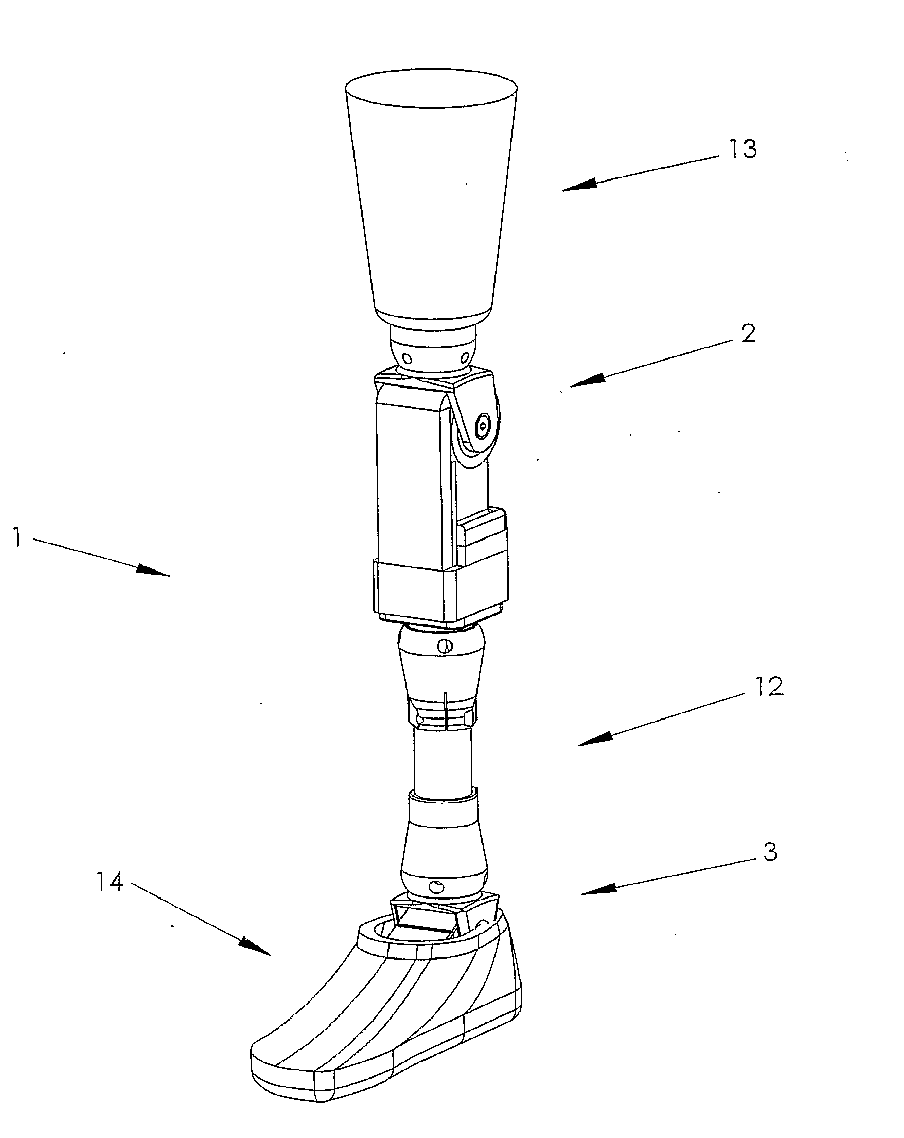
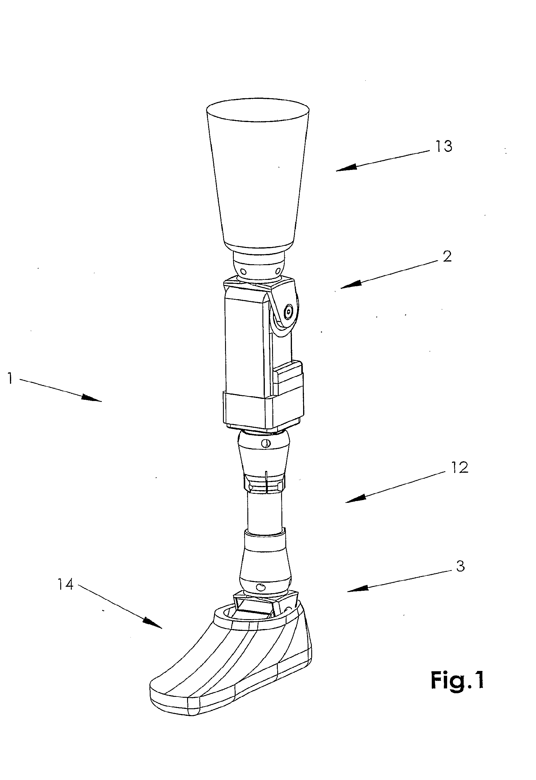
[0056]FIG. 1 shows a leg prosthesis system 1 with both knee joint 2 and ankle joint 3 according to the invention and a method of performing a gait cycle with a leg prosthesis system. A prosthesis wearer can attach the prosthesis to the amputated leg by means of the leg-enclosing socket 13. Furthermore the socket 13 is attached to the movable knee joint 2 in a suitable manner and the knee joint is connected to the ankle joint 3 by interconnecting elements 12 or the like. A foot prosthesis 14 is attached to the ankle joint 3 and can turn about the ankle joint 3. Additional components that may be included in a leg prosthesis system are shock absorbers, angularly adjustable couplings etc.

[0057]Most of the people with an amputated leg have lost their leg below the knee joint. The present leg prosthesis system and / or method can be used by prosthesis wearers who need a prosthesis with both knee joint and ankle joint, but the invention can also be used for a prosthesis with only an ankle jo...


PUM


Abstract

A lower limb prosthesis system and a method of controlling the prosthesis system to replace a missing lower extremity of an individual and perform a gait cycle are disclosed. The prosthesis system has a controller, one or more sensors, a prosthetic foot, and a movable ankle joint member coupled to the prosthetic foot. The movable ankle joint member comprises a hydraulic damping system that provides the ankle joint member damping resistance. The controller varies the damping resistance by providing volumetric flow control to the hydraulic damping system based on sensor data. In one embodiment, the hydraulic damping system comprises a hydraulic piston cylinder assembly, hydraulic fluid, and a valve to regulate the fluid. In one embodiment, the controller alters the damping resistance by modulating the valve to vary the hydraulic fluid flow within the hydraulic piston cylinder assembly of the movable ankle joint member based on sensor data.

Description

CROSS-REFERENCE TO RELATED APPLICATIONS[0001]This application is a continuation application of U.S. patent application Ser. No. 11 / 887,374, entitled COMBINED ACTIVE AND PASSIVE LEG PROSTHESIS SYSTEM AND A METHOD FOR PERFORMING A MOVEMENT WITH SUCH A SYSTEM, and filed Jul. 30, 2009, which is a national stage entry of International Patent Application No. PCT / SE2006 / 000445, entitled COMBINED ACTIVE AND PASSIVE LEG PROSTHESIS SYSTEM AND A METHOD FOR PERFORMING A MOVEMENT WITH SUCH A SYSTEM, and filed Apr. 18, 2006, the entireties of which are incorporated by reference herein.BACKGROUND[0002]1. Field[0003]The present invention relates generally to a method for a combined active and passive leg prosthesis system and a combined active and passive leg prosthesis system for replacing a missing lower extremity of an individual to perform a gait cycle (take a step) by the leg prosthesis system. The leg prosthesis system has at least one movable joint and a drive unit to drive the movable joint...

Claims


Application Information

Patent Timeline
Patent Type & Authority Applications(United States)
IPC IPC(8): A61F2/68A61F2/66
CPCA61F2/64A61F2/66A61F2/68A61F2/72A61F2002/607A61F2002/6818A61F2002/704A61F2002/705A61F2002/741A61F2002/745A61F2002/748A61F2002/7625A61F2002/763A61F2002/764A61F2002/7655A61F2/70A61F2/6607A61F2/60A61F2/741A61F2/74A61F2/748A61F2002/6614A61F2002/5038
Inventor GRAMNAES, LISA
Owner OSSUR HF
Learn More