Eureka AIR delivers breakthrough ideas for toughest innovation challenges, trusted by R&D personnel around the world.

Method for Controlling a Motor Vehicle Brake System

a brake system and motor vehicle technology, applied in the direction of braking systems, instruments, analogue processes for specific applications, etc., can solve the problems of reducing the torque which is taken up by a generator, limiting the recovered electrical energy, and reducing the efficiency of the recuperation. the effect of efficiency level optimization, increased electrical drive range, and greater deceleration

Active Publication Date: 2013-08-08
CONTINENTAL TEVES AG & CO OHG
View PDF3 Cites 14 Cited by
  • Summary
  • Abstract
  • Description
  • Claims
  • Application Information

AI Technical Summary

Benefits of technology

The patent describes a way to control the brakes of a vehicle with friction brakes on at least one axle using an electric machine. This allows for more efficient usage of the regenerative braking torque to convert kinetic energy into electrical energy. The system can also increase the regenerative deceleration even if the brake pedal position and force are unchanged.

Problems solved by technology

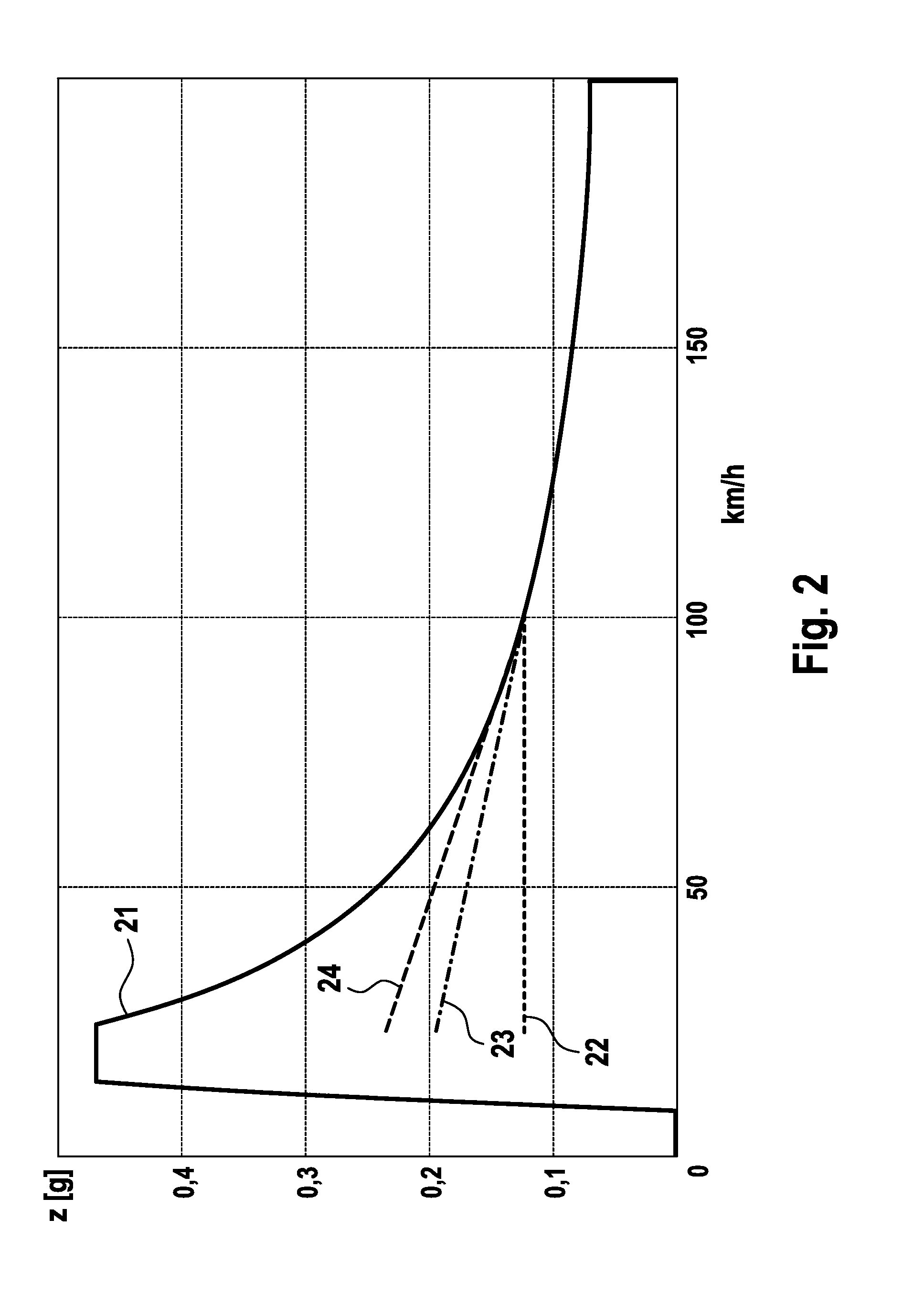
Furthermore in the case of constant generator power, the torque which is taken up by a generator decreases significantly as the speed increases, wherein energy recovery is no longer possible below a limiting speed of approximately 15 km / h.
If the ratio between the regenerative braking torque and the braking torque generated by friction brakes is constant over the entire braking process, this restricts the recovered electrical energy, i.e. the efficiency level of the energy recovery, also referred to as recuperation, is low.
If a conventional brake system is used, a simple reduction of pressure at the friction brakes is, however, not readily possible.

Method used


Image

  • Method for Controlling a Motor Vehicle Brake System
  • Method for Controlling a Motor Vehicle Brake System
  • Method for Controlling a Motor Vehicle Brake System

Examples


Embodiment Construction

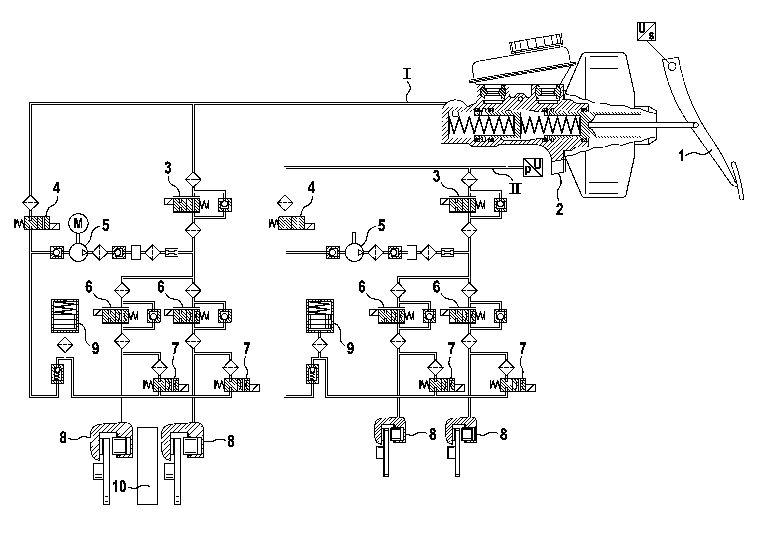
[0032]FIG. 1 shows a regenerative brake system which is suitable for carrying out the method according to the invention. The brake pedal 1 which is activated by the driver acts directly on a tandem master cylinder 2 which is operated with or without auxiliary force. Said tandem master cylinder 2 builds up pressure in two essentially identical brake circuits I and II, wherein these can be assigned to the wheels either on an axle basis (front and rear) or else diagonally. The brake fluid flows through isolating valves 3 and inlet valves 6 into the brake cylinders 8 which apply a frictional braking force to the wheels. If the outlet valves 7 are opened, brake fluid can be discharged into the low-pressure accumulators 9. The hydraulic pumps 5 permit a pressure built up which is independent of the driver, wherein for this purpose the electronic switchover valves 4 are opened and the isolating valves 3 are closed. On one of the axles there is an electric generator 10 which permits electri...


PUM


Abstract

A method in which open- or closed-loop control of a motor vehicle brake system is carried out having friction brakes on the wheels of at least one axle, wherein the brake pressure generating means for the wheels of at least one axle are in a direct operative connection to the brake pedal, and at least one electrical machine is in an operative connection to at least one axle which can be used by applying an electrically regenerative braking torque for converting kinetic energy into electrical energy. In order to raise the efficiency level of the recuperation, the regenerative deceleration is increased even in the case of an unchanged brake pedal position and / or brake pedal force, and a motor vehicle brake system which is open-loop or closed-loop controlled.

Description

CROSS-REFERENCE TO RELATED APPLICATIONS[0001]This application claims priority to German Patent Application No. 10 2010 041 853.6, file Oct. 1, 2010 and PCT / EP2011 / 066196, filed Sep. 19, 2011.FIELD OF THE INVENTION[0002]The invention relates to a method of controlling a motor vehicle brake system.BACKGROUND OF THE INVENTION[0003]Regenerative brake systems in motor vehicles make it possible for at least a portion of the energy applied during braking to be stored in the vehicle and re-used for driving the vehicle. As a result, the energy consumption of the vehicle overall can be lowered and the operation can therefore be made more economical. Motor vehicles with a regenerative brake system generally have different types of brake actuators for this purpose.[0004]In this context, hydraulic friction brakes such as are known from conventional motor vehicles and an electrically regenerative brake are generally used. The brake pressure for the friction brakes is applied via a brake pressure ...

Claims


Application Information

Patent Timeline
Patent Type & Authority Applications(United States)
IPC IPC(8): B60L7/18
CPCB60L7/18B60L7/26B60T1/10B60T8/267B60T13/586B60T2220/04Y02T10/56B60T2270/608B60W10/08B60W10/188B60W30/18127B60W2520/10B60W2710/083B60T2270/604Y02T10/40Y02T10/84B60L7/10B60L7/24B60T8/17B60T8/26B60T13/58
Inventor BILLER, HARALDSCHOENBOHM, ALEXANDER
Owner CONTINENTAL TEVES AG & CO OHG
Why Eureka
Eureka Blog
Learn More