Eureka AIR delivers breakthrough ideas for toughest innovation challenges, trusted by R&D personnel around the world.

Dust detection system

Active Publication Date: 2013-08-15
AB ELECTROLUX
View PDF1 Cites 0 Cited by
  • Summary
  • Abstract
  • Description
  • Claims
  • Application Information

AI Technical Summary

Benefits of technology

The objective of the invention is to provide an effective way to indicate that a full dustbin is connected to a cyclonic type dust separation chamber. This is important because when the dustbin is full, dust accumulates at the bottom of the chamber, where it cannot enter the bin. The strong cyclonic airstream keeps the walls of the chamber clean, minimizing dust contamination and improving the accuracy of dust detection systems.

Problems solved by technology

However, a common problem for vacuum cleaners with a separate dustbin is that the user forgets to empty the dustbin before the critical level is reached, which results in unnecessary clogging of filters and other parts of the vacuum cleaner.
The consequences of this are loss of cleaning performance and increased amount of maintenance of e.g. the main filter and filter screen.
The optical dust indicators are sensitive to dust getting stuck somewhere in the optical path of the detection system, as this blocks the light signal.
However, if there is accumulated debris, the electromagnetic signal is blocked with the periodicity of the encircling debris, which also may indicate a full dustbin.
Further, another possible situation is when debris is temporarily encircling the bottom portion of the dust separation chamber and blocking the electromagnetic signal with a periodicity instead of a full time blocked electromagnetic signal.

Method used


Image

  • Dust detection system
  • Dust detection system
  • Dust detection system

Examples


Embodiment Construction

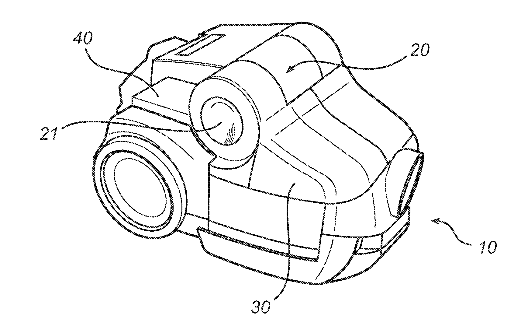
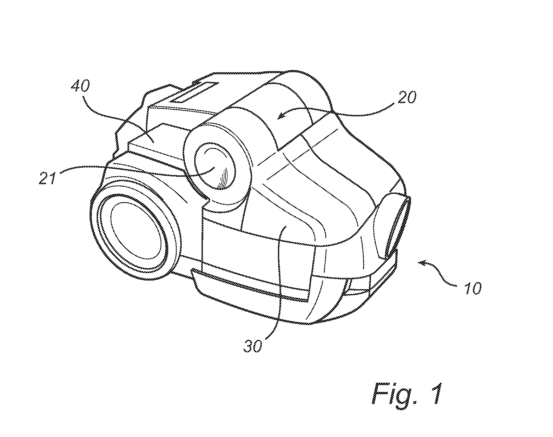
[0026]FIG. 1 illustrates a vacuum cleaner 10 of canister type which has a housing on which a dust separation chamber 20 of cyclone type is arranged. The dust separation chamber 20 is at its bottom connected to a dustbin 30 and a dust detector unit 40. The vacuum cleaner 10 typically comprises components such as a power unit, a vacuum source, a suction pipe, a floor nozzle etc. (not shown) for achieving the dust and dirt cleaning capability of the vacuum cleaner. However, because these dust and / or dirt sucking operation principles of the vacuum cleaner are not critical to the implementation of the present invention, detailed description thereof is omitted.

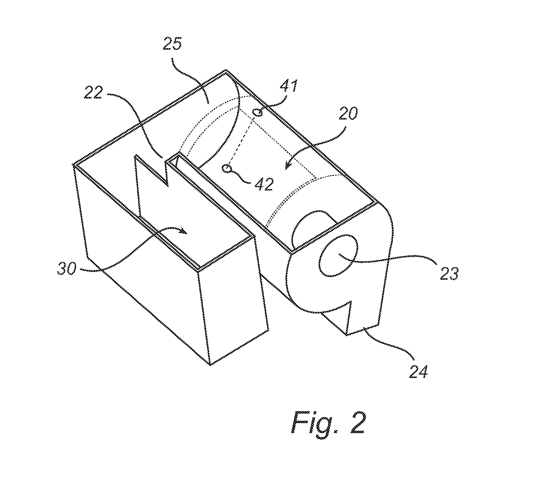
[0027]To continue, and with reference to FIG. 2, the dust separation chamber 20 is utilized to separate dust and dirt from a dust laden air stream typically entered into the vacuum cleaner via the floor nozzle and into the dust separation chamber 20 via an inlet 24. The dust separation chamber 20 is here substantially cylindrical, h...


PUM


Abstract

There is provided a dust detection system for a vacuum cleaner comprising a dust separation chamber (20) of cyclone type and having a separate dustbin (30) for collecting separated dust. The dust separation chamber is adapted to provide a generally cyclonic airflow for separating dust from a dust laden air stream, and is at a bottom (25) of the dust separation chamber connected via an outlet (22) to the dustbin. The dust detection system further comprises an emitter (41) positioned to emit an electromagnetic signal into the dust separation chamber during operation of the vacuum cleaner, and a receiver (42) positioned to receive the electromagnetic signal. The inventive concept is based on an understanding that when the dustbin becomes full, dust accumulates at the bottom of the dust separation chamber, i.e. stays rotating at the bottom, since it cannot enter the dustbin. The emitter and receiver are positioned in a bottom portion (26) of the dust separation chamber and are arranged to detect dust accumulating at the bottom portion during operation of the vacuum cleaner, thereby providing an indication of the dustbin being full.

Description

TECHNICAL FIELD[0001]The present invention generally relates to a dust detection system for use in vacuum cleaners that employ a cyclonic type dust separation chamber, and more particularly to a dust detection system for indicating a full dustbin.BACKGROUND OF THE INVENTION[0002]Vacuum cleaners that employ a cyclonic cleaning system, such as upright and canister vacuum cleaners, stick vacuums, central vacuums etc. are common on the market today. Dust from the dust laden airstream which is sucked into the vacuum cleaner is separated in a dust separation chamber and collected in a dustbin, which must be frequently emptied by the user. As long as the dust level in the dustbin is below a critical level, normal functionality of the dust separation in the vacuum cleaner is provided.[0003]However, a common problem for vacuum cleaners with a separate dustbin is that the user forgets to empty the dustbin before the critical level is reached, which results in unnecessary clogging of filters a...

Claims


Application Information

Patent Timeline
IPC IPC(8): A47L9/28
CPCA47L9/1683A47L9/19A47L9/1608A47L9/2857A47L9/2894A47L9/2815
Inventor JONSSON, STEFANSJOBERG, FREDRIK
Owner AB ELECTROLUX
Why Eureka
Eureka Blog
Learn More