Vacuum Drying Of Heat Exchanger Tubes

a heat exchanger tube and vacuum drying technology, which is applied in the direction of drying machines with progressive movements, lighting and heating apparatus, furnaces, etc., can solve the problems of volatile organic compounds that are flammable, and achieve the effect of safe removal of solvents

Inactive Publication Date: 2013-08-15
CARRIER CORP
View PDF4 Cites 9 Cited by
  • Summary
  • Abstract
  • Description
  • Claims
  • Application Information

AI Technical Summary

Benefits of technology

[0007]In one aspect, a process is provided for safely removing solvent from a solvent wetted surface of a he

Problems solved by technology

It is important that all the solvent be removed as the presence of solvent is detrimental to the performance of the lubricant in facilitating the subsequent passage of the mandrel through the tu

Method used


Image

  • Vacuum Drying Of Heat Exchanger Tubes
  • Vacuum Drying Of Heat Exchanger Tubes
  • Vacuum Drying Of Heat Exchanger Tubes

Examples


Embodiment Construction

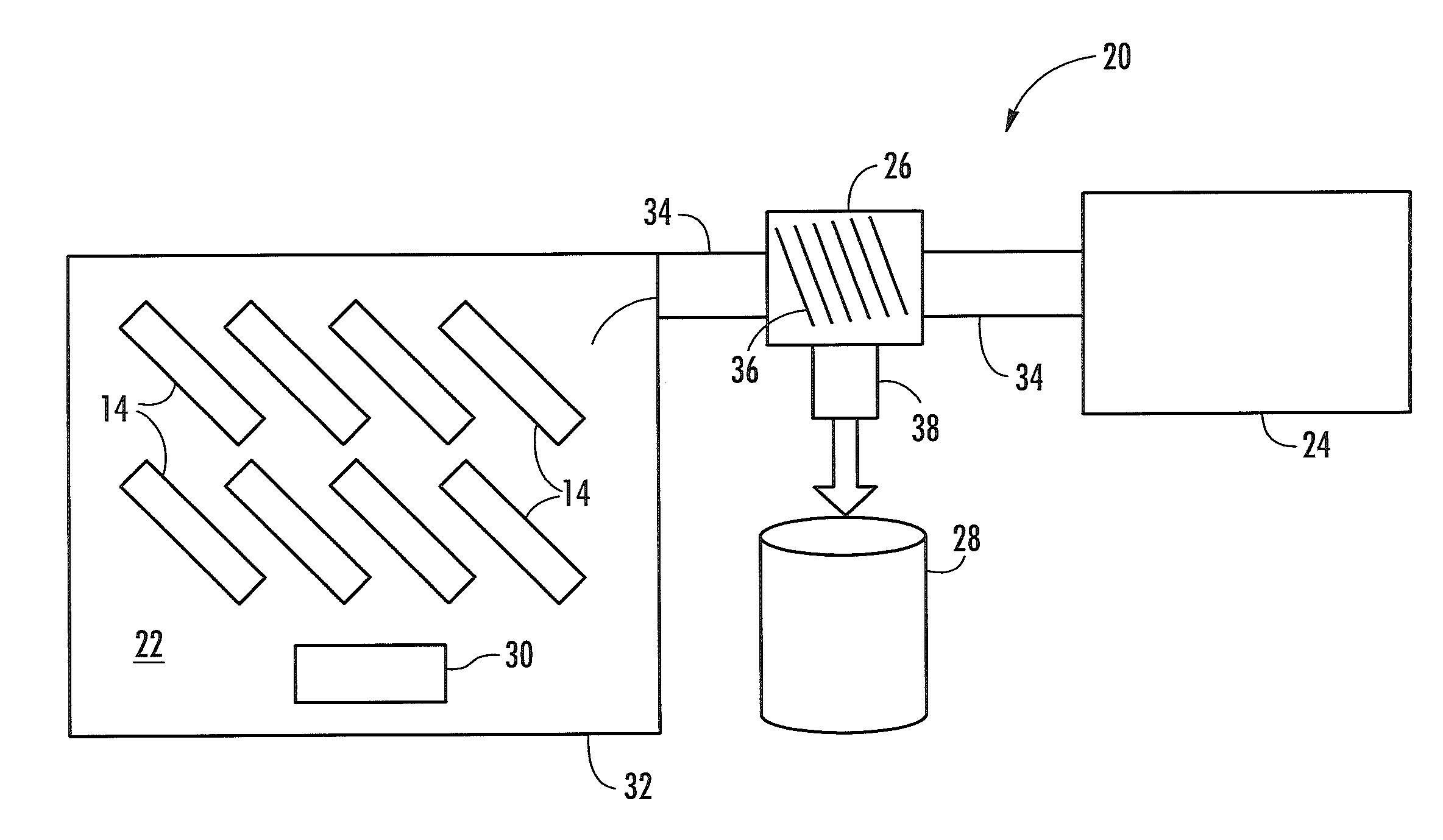
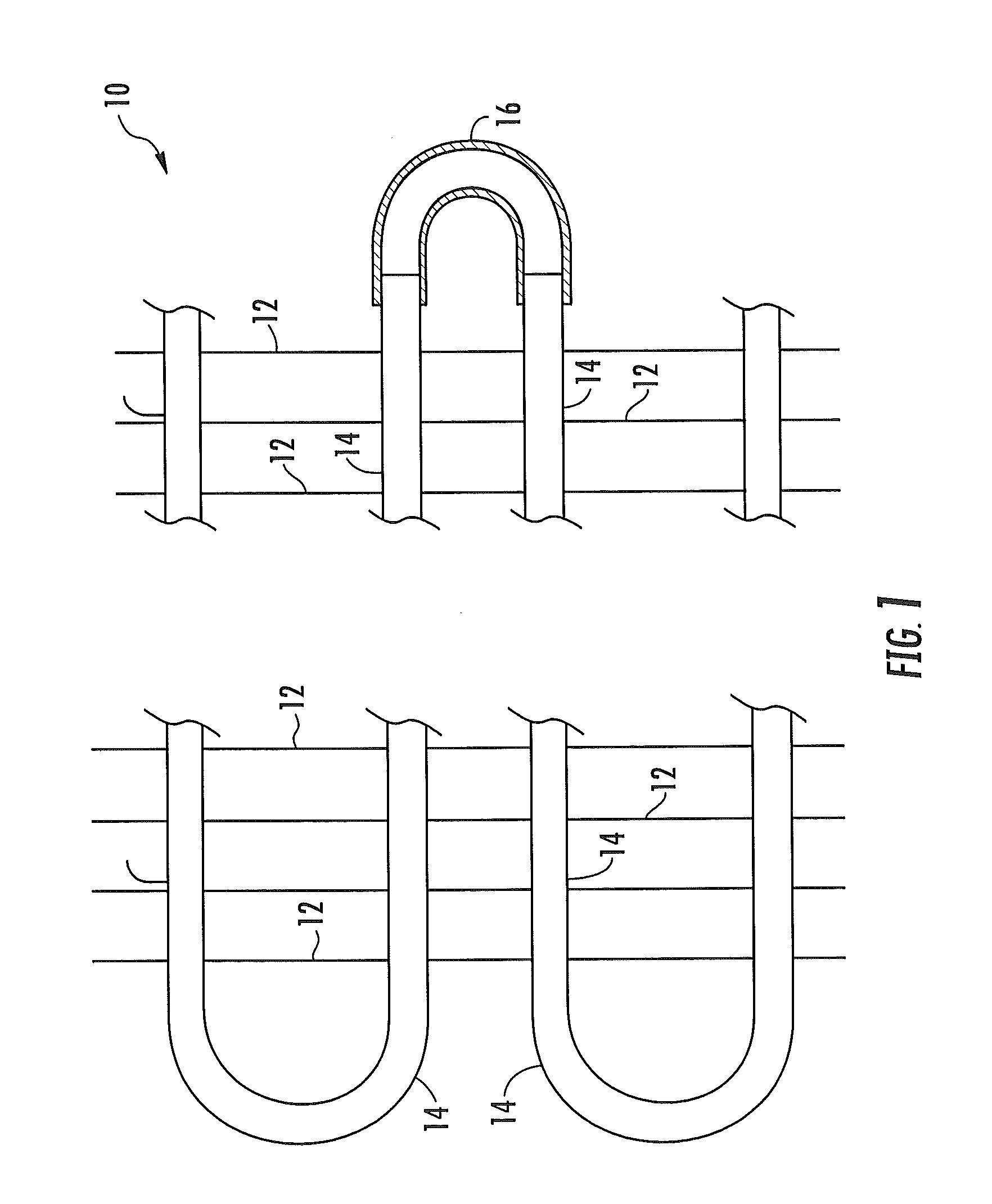
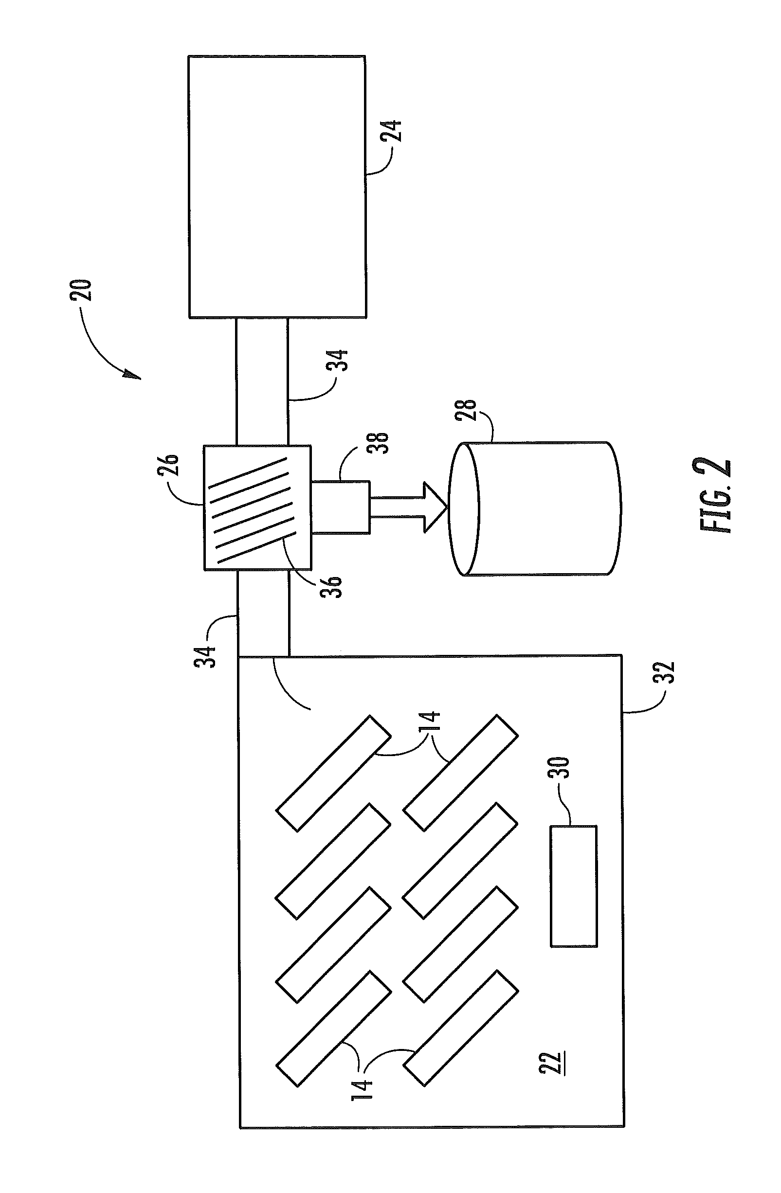
[0016]Referring initially to FIG. 1, there is depicted an exemplary embodiment of a finned tube coil heat exchanger 10 including a plurality of fins 12 and a plurality of heat exchange tubes 14 extending through the plurality of fins 12. The heat exchange tubes 12 are generally disposed in an array of spaced rows and spaced columns. Each heat exchange tube 14 defines an interior fluid flow passage. In the embodiment of the finned tube coil heat exchanger depicted in FIG. 1, the tube coil is formed of a plurality of hairpin tubes interconnected by generally U-shaped return bends 16 to form one or more fluid flow circuits through the tube coil.

[0017]Each fin 12 of the plurality of fins comprises a relatively thin metal sheet having a plurality of holes punched therein in a pattern matching the tube array. The fins 12 are assembled in spaced relationship on the plurality of heat exchange tubes 14 with the heat exchange tubes 14 received in and passing through the holes of a plurality o...


PUM


Abstract

A method and an apparatus are disclosed for removing a solvent from a solvent wetted surface of a heat exchange tube. The method includes placing the heat exchange tube in a vacuum chamber, evacuating the vacuum chamber to a lower pressure at which the solvent boils to a vapor, and reclaiming the solvent vapor. The method may include heating the heat exchange tube within the vacuum chamber to a temperature of at least room temperature, but below the solvent's flash point temperature. The apparatus includes a vacuum chamber, a vacuum pump for evacuating the vacuum chamber and a solvent reclaimer for recovering solvent vapor. The apparatus may also include an infrared heater, a radiant heater or other non-flame heater. The method and apparatus may be used for removing solvent from a heat exchange tube having an inside surface wetted with a solvent carrying a dry lubricant.

Description

CROSS-REFERENCE TO RELATED APPLICATIONS[0001]This application claims the benefit of U.S. provisional patent application Ser. No. 61 / 596,812 filed Feb. 9, 2012, the entire contents of which are incorporated herein by reference.BACKGROUND OF THE INVENTION[0002]Exemplary embodiments pertain generally to manufacture of heat exchanger tubes and, more particularly, to the removal of residual solvent from a prelubricant applied to heat exchanger tubes during the manufacturing process.[0003]Tube coil heat exchangers are commonly used in many industrial applications wherein it is desired to transfer heat from one fluid to another fluid, one fluid passing through the heat exchange tubes and the other fluid passing over the heat exchange tubes. For example, evaporators, condensers, and other heat exchanger of various heating, ventilating and air conditioning and refrigeration (HVAC&R) equipment are conventionally tube coil heat exchangers. Typically, a plurality of fins are mounted to the heat...

Claims


Application Information

Patent Timeline
IPC IPC(8): F26B5/04
CPCF26B3/30F26B5/04F26B25/006
Inventor KONKLE, ERIC
Owner CARRIER CORP
Why Eureka
Try Eureka