Tower and wind turbine generator having the same

a technology of wind turbine generator and turbine, which is applied in the direction of buildings, buildings, buildings, etc., can solve the problems of increasing the outer diameter of the tower, reducing the service life of the tower, so as to reduce the manufacturing and construction costs, reduce the displacement, and improve the yield strength of the flange junction.

Inactive Publication Date: 2013-08-15
MITSUBISHI HEAVY IND LTD
View PDF7 Cites 15 Cited by
  • Summary
  • Abstract
  • Description
  • Claims
  • Application Information

AI Technical Summary

Benefits of technology

[0023]Since the tower sections are bound to each other by way of the tensile member stretched between the supporting parts, even when the tower sections have some tolerances, by adjusting the tensile force of the tensile member, the tensile member can be stretched with a predetermined tensile force. For this reason, a high manufacturing accuracy is not required to the tower section, thereby enabling reduction of manufacturing and construction costs of the tower.
[0024]According to the present invention, the tensile member may be stretched in a substantially vertical direction, at least one of the first supporting part and the second supporting part may include a groove or a through hole into which the tensile member is inserted, a socket is fixedly attached to an end of the tensile member, which corresponds to the groove or the through hole, and the socket may be locked to the supporting part, thereby restricting displacement with respect to the supporting part.
[0025]By providing the groove or the through hole into which the tensile member is inserted in the supporting part, the socket can be easily locked to the supporting part. That is, by making the shape and the size of the socket that cannot pass through the groove or the through hole when the tensile force is generated in the tensile member, the socket can be firmly locked to the supporting part.
[0026]Although the socket provided at the end of the tensile member is locked to the supporting part, when no tensile force is generated in the tensile member or the applied tensile force is small, locking between the supporting part and the socket can be easily released by using the groove or the through hole.

Problems solved by technology

The present inventor found, in Patent Literature 1, a problem that further improvement in the yield strength of a flange junction cannot be expected, and it has become difficult to meet a required yield strength.
Although the yield strength required to address the load increases with an increase in size of the wind turbine generator, it is difficult to make the outer diameter of the tower larger than the existing sizes due to limitations upon transport.
Under such a situation, in the case of a flange joint as disclosed in Patent Literature 1, the outer diameter of the flange is also limited by the outer diameter of the tower having transport limitations, and thus it is difficult to increase the number of bolts arranged at the flange.
As a result, further improvement in the yield strength of the flange junction cannot be expected, and it has become difficult to meet a required yield strength.
Further, the present inventor found, in Patent Literature 2, problems that a high assembling accuracy is required to connect the tower sections and that a high manufacturing accuracy of the tower section is required to sufficiently reduce misalignment between the butted tower sections, thereby greatly increasing manufacturing costs of the tower.
In addition, the cylindrical tower section is molded by rounding and joining a steel plate, and according to this manufacturing method, it is difficult to make the sectional shape of the tower section into a perfect circle.
Accordingly, implementation of the invention described in Patent Literature 2 leads to a significant increase in costs.

Method used


Image

  • Tower and wind turbine generator having the same
  • Tower and wind turbine generator having the same
  • Tower and wind turbine generator having the same

Examples


first embodiment

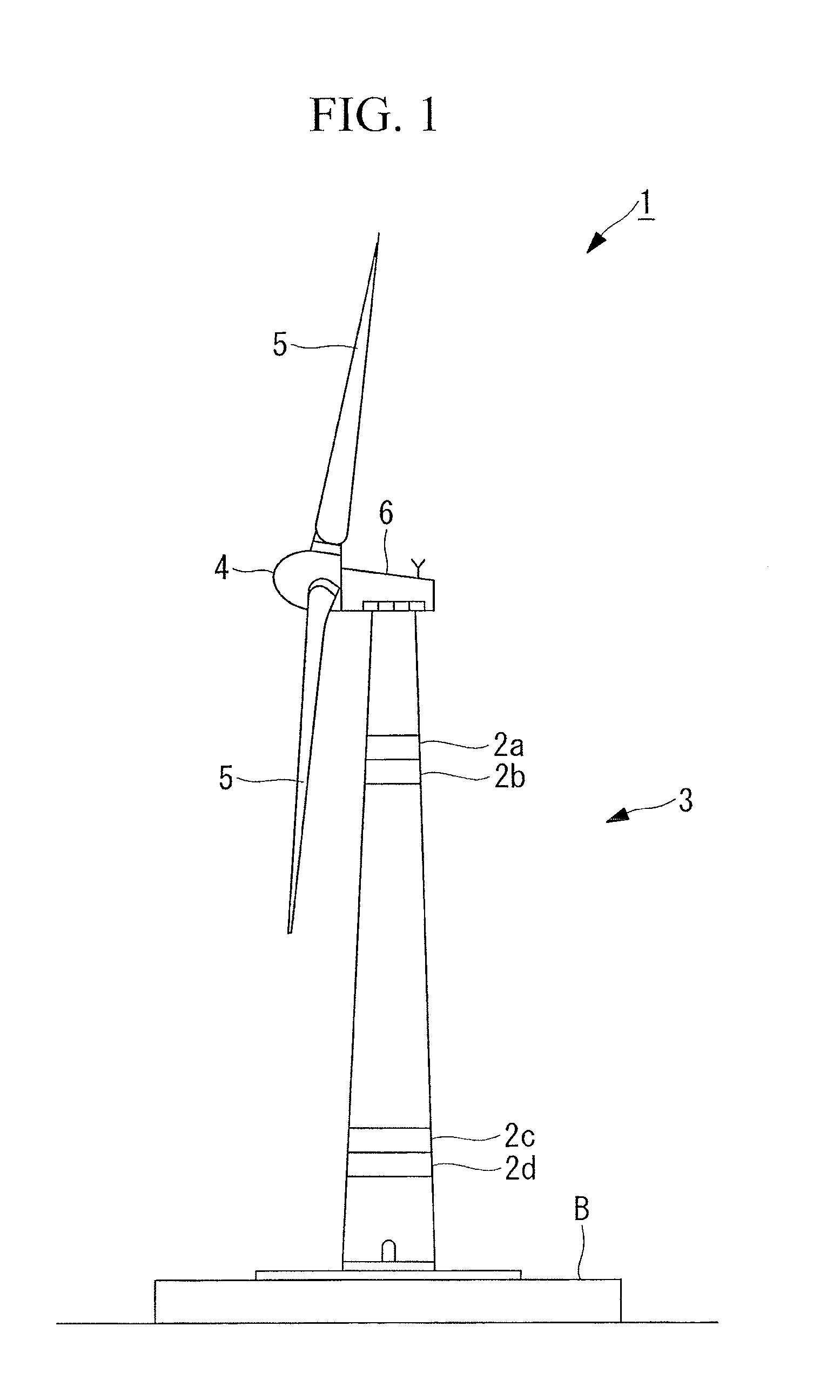
[0056]As shown in FIG. 1, a wind turbine generator 1 includes a tower 3 vertically installed on a base B, a nacelle 6 installed at an upper end of the tower 3, and a rotor head 4 provided at the nacelle 6 so as to be rotatable about a substantially horizontal axis. A plurality of (for example, three) wind turbine rotary blades 5 are radially attached to the rotor head 4 around the rotation axis of the rotor head 4. Thereby the force of the wind on the wind turbine rotary blades 5 from the direction of the rotation axis of the rotor head 4 is converted into power for rotating the rotor head 4 about the rotation axis.

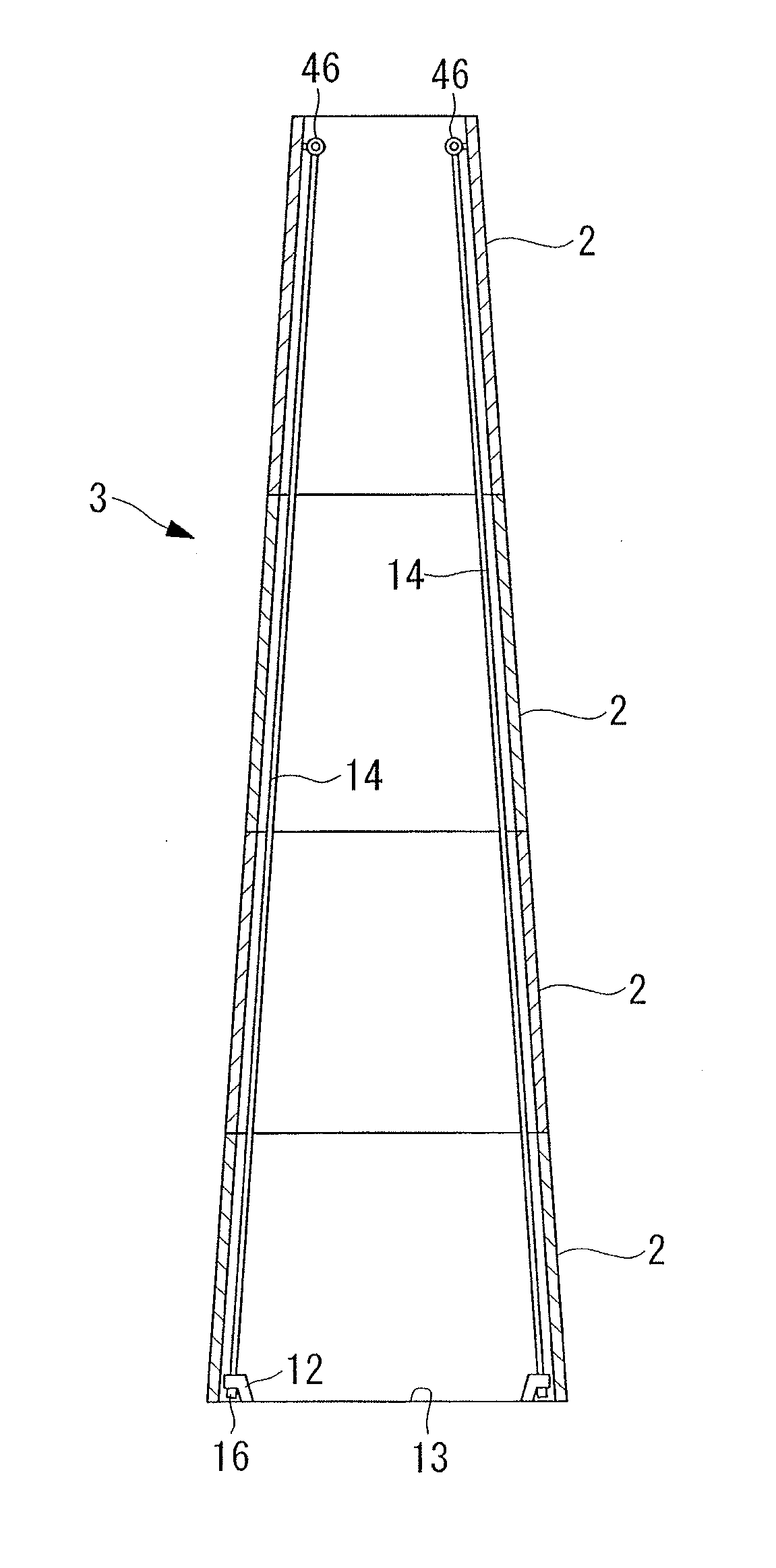
[0057]In the first embodiment of the present invention, the tower 3 is configured by stacking and joining a plurality of tower sections 2 to each other in the vertical direction, and is provided in the wind turbine generator 1.

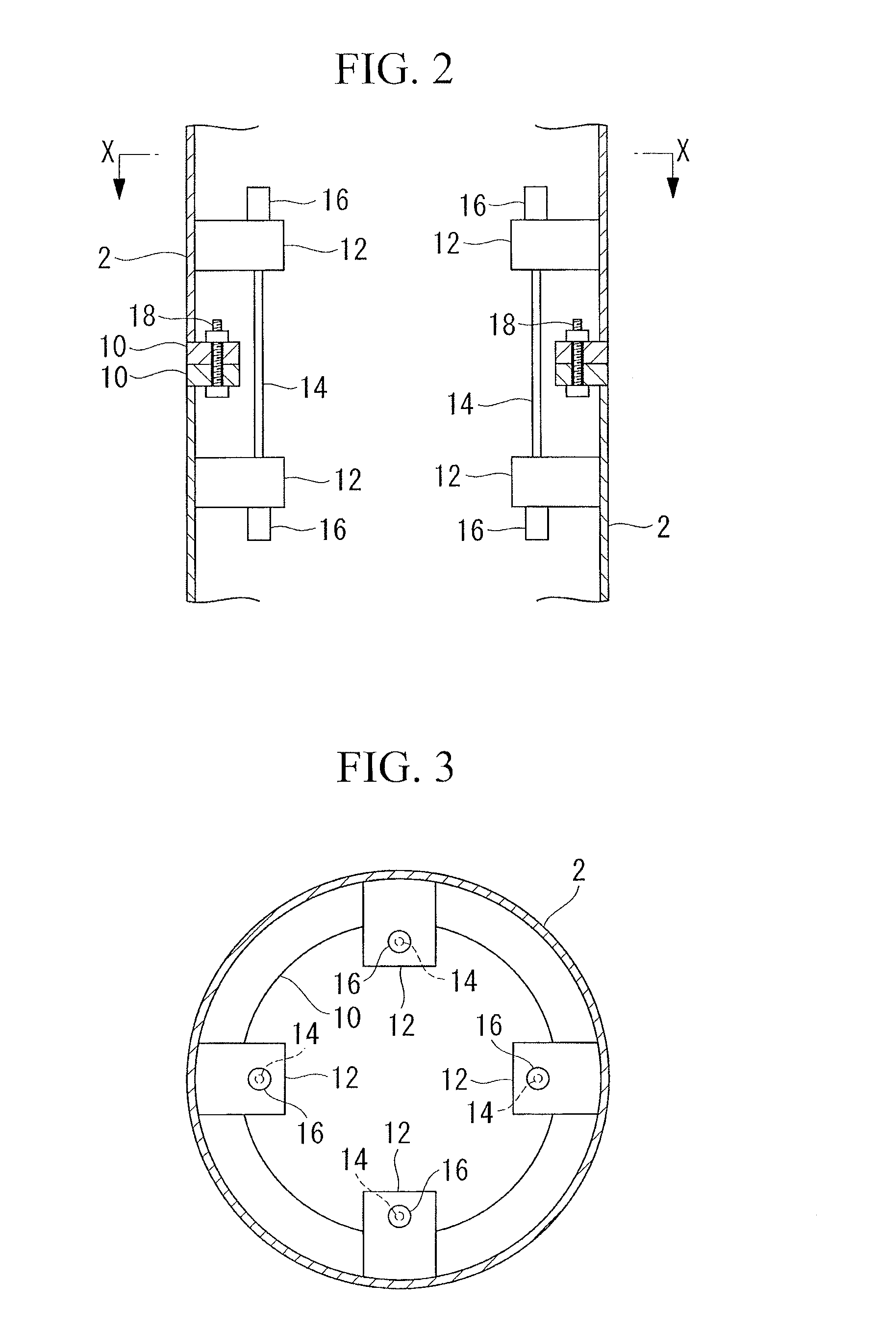
[0058]As shown in FIG. 2, a flange 10 is provided at an end of the tower section 2, and at a junction where the ends of the tower sections 2 are bu...

second embodiment

[0080]FIG. 7 shows a fixing bracket used in a tower in accordance with a second embodiment of the present invention. The same members as those in the above-mentioned embodiment are denoted by the same reference symbols and redundant description thereof is not repetitively provided.

[0081]In the present embodiment, the fixing bracket 12d has a groove 20 for inserting the wire rope 14 thereinto. The groove 20 extends substantially linearly outward in the radial direction (toward the left in FIG. 7) from a free end of the fixing bracket 12d (inner circumferential end in cross section of the tower; right end in FIG. 7), and terminates substantially at the center of the fixing bracket 12d. A width of the groove 20 is substantially constant in the extending direction and is larger than a diameter of the wire rope 14. However, the width of the groove 20 is smaller than a width of a socket base 16a serving as a base of the socket 16, and by provision of the groove 20, the socket 16 is locked...

third embodiment

[0085]FIG. 9 shows a fixing bracket used in a tower in accordance with a third embodiment of the present invention. The same members as those in the above-mentioned embodiments are denoted by the same reference symbols and redundant description thereof is not repetitively provided.

[0086]In the present embodiment, the socket 16 is rectangular in a plan view, specifically, oblong. A through hole 22 for inserting the wire rope 14 thereinto is formed in the fixing bracket 12e. The through hole 22 is oblong like the socket 16 and has a dimension that enables insertion of the socket 16.

[0087]A concave part 22a dented in the plate thickness direction is provided in an upper surface of the fixing bracket 12e. The concave part 22a is in an oblong shape that is slightly larger than the socket 16 in a plan view, and the socket 16 is partially or entirely fitted into the concave part 22a. A long side of the oblong concave part 22a is shifted from a long side of the oblong through hole 22 in the...


PUM


Abstract

Provided are a tower that has a sufficient yield strength and enables connection between tower sections without requiring a high manufacturing accuracy of the tower sections, and a wind turbine generator having the tower. The tower includes a plurality of tower sections formed by dividing the tower along planes that are parallel to a horizontal plane, and is constituted by connecting end surfaces of the tower sections to each other. The tower further includes a tensile member that has one end supported by a first supporting part at a first tower section among the tower sections, has another end supported by a second supporting part at a second tower section among the tower sections or at a tower base on which the tower is vertically installed, and is stretched along an inner wall of the tower sections so as to have a predetermined tensile force.

Description

BACKGROUND OF THE INVENTION[0001]1. Field of the Invention[0002]The present invention relates to a tower and a wind turbine generator having the tower.[0003]2. Description of Related Art[0004]Generally, for example, a tower in a wind turbine generator or the like is constructed by stacking and connecting a plurality of tubular tower sections in the vertical direction on a construction site. This is because a tower having several tens of meters in length is used for such a wind turbine generator, and thus it is difficult to transport a completed tower to a construction site. For this reason, the tower is transported to the construction site in a state in which the tower is divided into the tower sections of transportable sizes.[0005]Generally, as disclosed in PCT International Publication No. WO 2009 / 028092 A1 (hereinafter referred to as “Patent Literature 1”), an axial end of each tower section has a flange, and a tower is constructed by joining the flanges to each other by use of a...

Claims


Application Information

Patent Timeline
Patent Type & Authority Applications(United States)
IPC IPC(8): E04H12/34E04H12/20E04H12/16
CPCE04H12/085E04H12/16
Inventor KAWABATA, MINORU
Owner MITSUBISHI HEAVY IND LTD
Why Eureka
Try Eureka