Measurement apparatus and method

a technology of measurement apparatus and crank angle, applied in the direction of apparatus for force/torque/work measurement, instruments, gymnastic exercise, etc., can solve the problem of not being able to present the direction and strength of power according to the crank angl

Active Publication Date: 2013-08-15
SHIMANO INC
View PDF2 Cites 44 Cited by
  • Summary
  • Abstract
  • Description
  • Claims
  • Application Information

AI Technical Summary

Benefits of technology

[0008]It is therefore, an object of the present invention to provide a measurement apparatus and a measurement method that can present the direction of power according to a crank angle.

Problems solved by technology

However, with the method disclosed in Patent Literature 1, there is a problem that is it not possible to present the direction and strength of power according to a crank angle.

Method used


Image

  • Measurement apparatus and method
  • Measurement apparatus and method
  • Measurement apparatus and method

Examples


embodiment 1

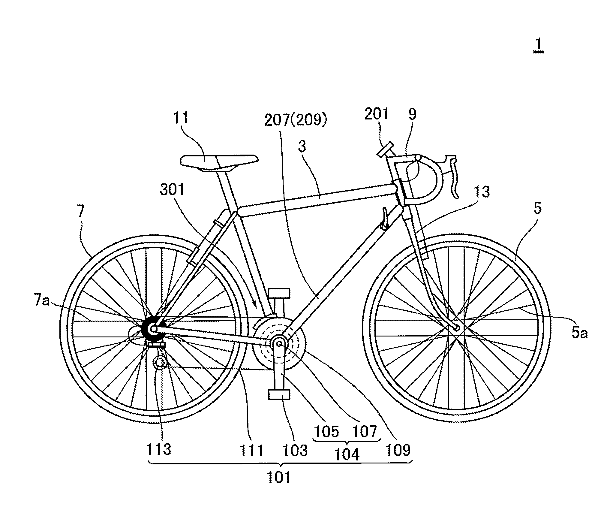
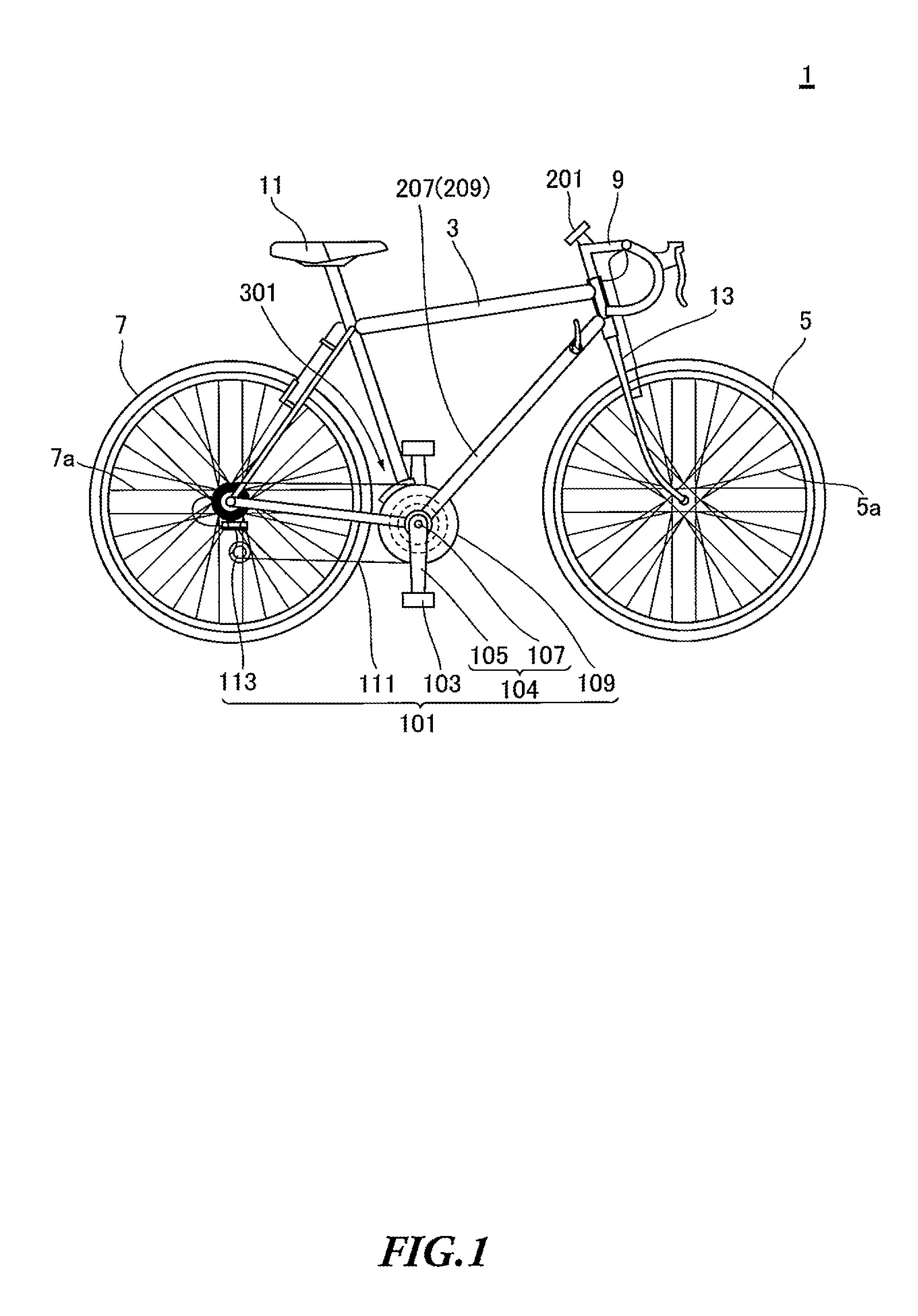
[0025]FIG. 1 is an overall view of a bicycle 1 according to Embodiment 1 of the present invention.

[0026]As shown in FIG. 1, the bicycle 1 includes a frame 3, a front wheel 5, a rear wheel 7, a handle 9, a saddle 11, a front fork 13 and a drive mechanism 101. The frame 3 is constituted by two trusses. The front fork 13 is rotatably connected to the front of the frame 3. The front fork 13 is connected to the handle 9. The front wheel 5 is rotatably connected to the lower end of the front fork 13. The front wheel 5 has a hub part, a spoke part and a tire part. The hub part is rotatably connected to the front fork 13. Then, the hub part and the tire part are connected through the spoke part. The rear end of the frame 3 is rotatably connected to the rear wheel 7. The rear wheel 7 has a hub part, a spoke part and a tire part. The hub part is rotatably connected to the frame 3. The hub part and the tire part are connected through the spoke part. The hub part of the rear wheel 7 is connecte...

embodiment 2

[0100]With the above-described Embodiment 1, a configuration has been explained where the MM storage part 353 (MM RAM 355) with a capacity large enough to prevent overflow is employed. However, if the MM storage 353 (MM RAM 355) with a too large capacity is employed, the cost increases. In addition, if the capacity is simply increased, it is not possible to solve the problem that the cycle computer (CC) 201 cannot correctly display the average power and the average amount of loss. Therefore, with Embodiment 2, to solve these problems, the measurement module (MM) 301 is provided with a gear change detecting part 381.

[0101]FIG. 9 shows a block diagram showing the cycle computer (CC) 201 and the measurement module (MM) 301 according to Embodiment 2.

[0102]FIG. 9 is basically the same as FIG. 3, and therefore overlapping descriptions will be omitted. As shown in FIG. 9, the measurement module (MM) 301 has a gear change detecting part 381. The gear change detecting part 381 can detect a g...

embodiment 3

[0115]With Embodiment 2, it is difficult to support a plurality of gears. In addition, with Embodiment 2, the average power and the average amount of loss can be calculated only after the crank 105 passes through the magnet 311a. Moreover, with Embodiment 2, the capacity of the MM storage part 353 has to be designed to support a change in the gear ratio. With Embodiment 3, these problems will be addressed.

[0116]FIG. 11 is a block diagram showing the cycle computer (CC) 201 and the measurement module (MM) 301 according to Embodiment 3.

[0117]FIG. 11 is basically the same as FIG. 3, and therefore overlapping descriptions will be omitted. As shown in FIG. 11, the measurement module (MM) 301 has a gear ratio detecting part 383. The gear ratio detecting part 383 can recognize the number of teeth of the changed gear. Therefore, when there is a gear change, it is possible to estimate how much the rotation speed of the crank 105 is changed.

[0118]The reason why the gear ratio detecting part 3...


PUM

PropertyMeasurementUnit
angleaaaaaaaaaa
angleaaaaaaaaaa
rotationaaaaaaaaaa

Abstract

A measurement module that measures force being applied to a man-powered machine includes: a strain sensor that detects strain of a crank of the bicycle configured to transmit force being applied from a user through the crank and one front gear selected among one or more front gears; an MM magnetic sensor that detects the crank passing through a predetermined position; and an MM control part. The MM control part calculates a rotation angle of the crank based on an elapsed time from a time the crank passes through the predetermined position that the sensor has detected, calculates force applied to the crank based on a strain amount of the crank that the strain sensor has detected, associates the rotation angle with the force applied to the crank to calculate distribution of the force applied from the user.

Description

CROSS-REFERENCES TO RELATED APPLICATIONS[0001]This application claims the benefit of PCT International Patent Application No. PCT / JP2010 / 068763, filed Oct. 22, 2010, which is incorporated herein by reference.BACKGROUND[0002]1. Technical Field[0003]The present invention relates to a measurement apparatus and a measurement method for measuring force applied to a man-powered machine having a crank, such as a bicycle, an exercise bike and so forth.[0004]2. Related Art[0005]Patent literature 1 discloses a technology for calculating power and calories-out and displaying and recording them, by detecting torque by a magnetostrictor and detecting a crank angle by an optical sensor.[0006]Patent Literature 1: Japanese Patent Application Laid-Open No. 2004-338653[0007]However, with the method disclosed in Patent Literature 1, there is a problem that is it not possible to present the direction and strength of power according to a crank angle.SUMMARY[0008]It is therefore, an object of the present...

Claims


Application Information

Patent Timeline
Patent Type & Authority Applications(United States)
IPC IPC(8): G01L3/10G01L3/02
CPCA63B24/0062A63B2225/20A63B2220/51A63B2220/58B62J99/00B62M3/00B62M6/50A63B69/16B62J2099/0013G01L3/1457G01L5/162G01L3/02G01L3/101B62J2099/002A63B71/0619A63B2220/805A63B2220/16B62J45/20B62J45/413
Inventor KODAMA, YASUTERUFUJITA, RYUJIROSHIODA, TAKEHIKOKAMETANI, RYUSHIN
Owner SHIMANO INC
Why Eureka
Try Eureka