Cycloidal transmissions

a cycloid transmission and rotor technology, applied in the direction of gears, mechanical equipment, rotary machine parts, etc., can solve the problems of unbalance of the two gear systems, inability to incorporate these bearings, and large eccentricities

Active Publication Date: 2013-08-15
UNIV NAT AUTONOMA DE MEXICO
View PDF5 Cites 16 Cited by
  • Summary
  • Abstract
  • Description
  • Claims
  • Application Information

AI Technical Summary

Benefits of technology

[0055]FIG. 6 is a mid-section view of a cyclodial magnetic gear transmission incorporating a balance wheel, according to the second embodiment.

Problems solved by technology

The incorporation of these bearings may not be feasible for large eccentricities.
One of the problems encountered in prior art cycloidal transmissions, whether it be with spur gears or with magnetic gears, is the unbalancing of the two gear system.
A disadvantage of cycloidal transmissions is the vibration due to the orbital movement of the mobile gear, given that its mass center is displaced in a circular trajectory which causes a centrifugal force of mw2r magnitude, where m represents the gear mass, w the angular speed of the crank, and r the radius of the circular trajectory, said force represented by a vector which also rotates at a speed w. A way to lower this vibration is by incorporating a second mobile gear propelled by a crank at 180° to the first.

Method used


Image

  • Cycloidal transmissions
  • Cycloidal transmissions
  • Cycloidal transmissions

Examples


first embodiment

Cycloidal Magnetic Transmission with Permanent Magnet Gears

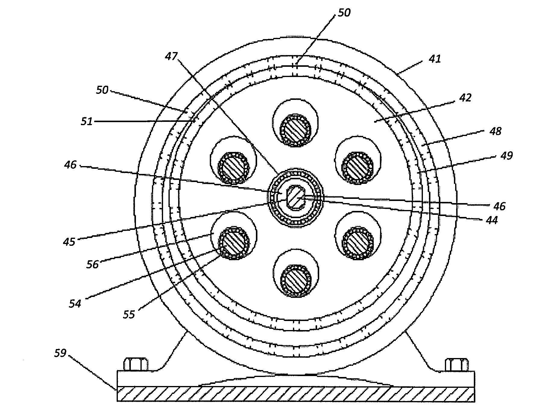
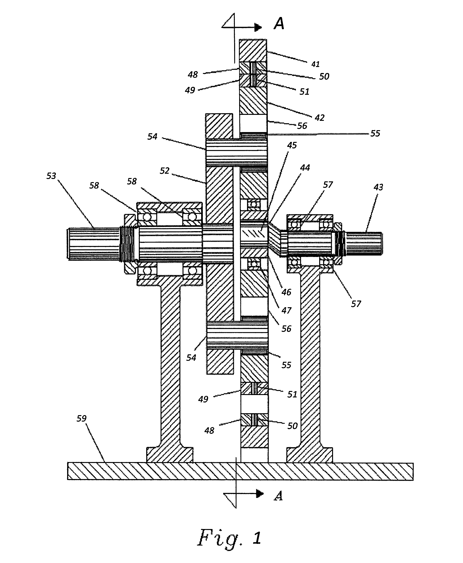
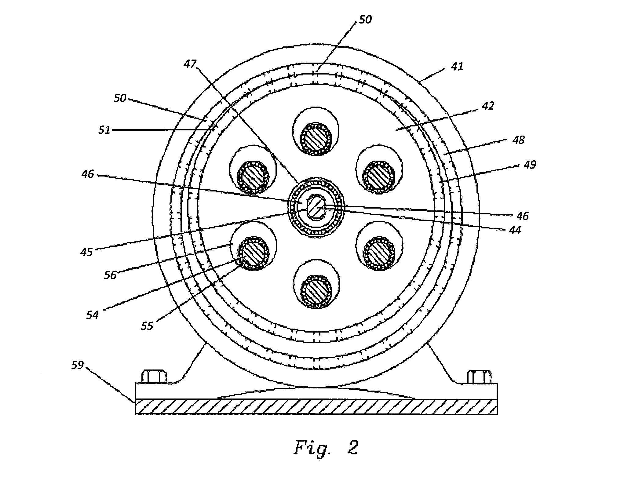
[0058]FIG. 1 is a view of the mid section of the transmission showing the fixed magnetic gear 41, the mobile magnetic gear 42, the high-speed shaft 43, having a throw at its end, forming a crank 44 with two flat parallel surfaces 45, that allow the central piece 46 on which gear 42 is mounted by means of bearing 47, to slide freely. Gear 41 has an internal ring of non-magnetic material 48 and gear 42 an external ring of non-magnetic material 49. Inserted permanently in ring 48 are an even number of permanent magnets 50, and a smaller even number of permanent magnets 51 in ring 49. With the exception of rings 48 and 49, gears 41 and 42 are made of a high magnetic permeability material. Disk 52 is rigidly attached to the low-speed shaft 53 and has rigidly attached to it a plurality of axial pins 54, each having a roller bearing 55. Each bearing 55 makes rolling contact with the surface of a hole 56 in gear 42. The number of ho...

second embodiment

[0063]This embodiment refers to a cyclodial transmission or to a cyclodial transmission system, in which a balance wheel is used to eliminate the unbalancing caused by the orbital movement of a mobile gear. The center of the balance wheel is displaced in a circular trajectory, and is propelled by a crank unto which said balance wheel is mounted by means of a bearing. The crank of the balance wheel with its elbow and the crank of the mobile gear with its elbow are part of a high-speed shaft and are diametrically opposed, that is, the crank of the balance wheel with its elbow is diametrically opposed to the crank of the mobile gear with its elbow, and thus the cranks are 180° from each other.

[0064]The balance wheel has an extension which has a ring shape, wherein an inner surface of the extension comes into contact with a cylindrical track made up by the outer surface of the fixed gear. This contact between the inner surface of the extension and the outer surface of the fixed gear gen...


PUM


Abstract

The present invention refers to a conventional spur gear transmission or magnetic gear transmission, with a cycloidal configuration. The magnetic gears include contact points such that the mobile gear rolls on the fixed gear. Alternatively, a balance wheel is incorporated, which generates a centrifugal force opposite to the one associated with the mobile gear, of equal magnitude and on the same plane as this latter one, thereby completely eliminating the unbalancing of the mechanism. The balance wheel is mounted on the high-speed shaft in a manner similar to the mobile gear, and has the freedom to displace itself radially through centrifugal effect in the opposite direction to the eccentric position of the center of the mobile gear until it presses against a fixed track over which it rolls, concentric with the fixed gear with an equal force, opposite and collinear with that produced by the mobile gear.

Description

FIELD OF INVENTION[0001]The present invention refers generally to transmissions, and more specifically to cycloidal transmissions with spur gears or magnetic gears, which function as speed reducers and amplifiers.BACKGROUND OF THE INVENTION[0002]In the cycloidal drives / transmissions generally used as speed reducers, a mobile gear with external teeth is propelled in a circular orbit by means of a crank of a high-speed input shaft. Said mobile gear is meshed with a fixed annular gear with internal teeth. The crank radius is equal to the eccentricity between the two gears.[0003]Typically, a coupling is used between the mobile gear and the low-speed output shaft, capable of mechanically transmitting the rotational movement of said mobile gear, but not the orbital translation of the same. In said coupling the torque transmission is accomplished by means of a number of axial rods uniformly distributed on a disc integrated to the low-speed shaft, which penetrate into an equal number of cir...

Claims


Application Information

Patent Timeline
Patent Type & Authority Applications(United States)
IPC IPC(8): F16F15/14
CPCF16F15/14F16F15/1478F16H1/32Y10T74/2121F16H2001/325F16H2001/328H02K49/102
Inventor CHICUREL UZIEL, RICARDOVAZQUEZ PEREZ, LUIS ALBERTOASCANIO GASCA, GABRIEL
Owner UNIV NAT AUTONOMA DE MEXICO
Why Eureka
Try Eureka