Photo voltaic generator panel, method and system

a generator panel and photovoltaic technology, applied in the direction of solar heat collectors, solar heat collector mounting/support, light and heating apparatus, etc., can solve the problems of high transportation and final installation cost, time-consuming method of fixation, disadvantage of a higher weight, etc., to achieve easy, fast and robust mechanical joining, the effect of maximizing the use of the insolation area

Active Publication Date: 2013-08-15
REC SOLAR
View PDF6 Cites 38 Cited by
  • Summary
  • Abstract
  • Description
  • Claims
  • Application Information

AI Technical Summary

Benefits of technology

[0027]A significant advantage of the present invention is that it allows the panels to be “frameless” since the support is provided on site at the installation location. In this document a frameless panel means a laminate without a conventional aluminium frame. The laminate can, however, be fitted with edge protection with essentially the same thickness as the laminate but does not provide the structural support of a frame. In order to maximize the use of insolation area, the attachment features may be arranged so that they do not extend beyond the edge of the back sheet. Some relatively minor extending of the attachment features beyond the back sheet edge(s) may be desired to establish a certain small gap between individual panels to promote convective cooling and also to assist in installation. Typically the attachment feature(s) will not extend beyond the edge of the back sheet by more than 10 millimetres.
[0028]The avoidance of the need for a frame provides significant contrast with the prior art outlined above. Thus, the present invention does not require the use of a frame, but instead has rear-side mounting members enabling easy, fast and robust mechanical joining of the panels to stiffening structures at the installation point. This is a much more effective method of obtaining a quality product by enhancing the stiffness of the structure at the point of intended installation.
[0029]The attachment features of the present invention can result in a sh

Problems solved by technology

In the production and fitting of solar panels to roofs of buildings, tracker structures or fixed ground mounting structures, transport and final installation costs are significant.
This requires assembly of a number of small parts at the installation site, which is a time-consuming method of fixation.
Another configuration is glass-glass laminates with adequate stiffness, but with the disadvantage of a higher weight.
The solar cells are generally vulnerable to stress, which may lead to micro-cracks and accompanying power loss.
However, the penalty with thicker glass is increased weight, reduced heat transfer properties, and more difficult handling and installation work.
If the height of the frame is increased, the penalty is greater packaging volume and associated transport costs.
Plastic is a relatively soft material an

Method used


Image

  • Photo voltaic generator panel, method and system
  • Photo voltaic generator panel, method and system
  • Photo voltaic generator panel, method and system

Examples


first embodiment

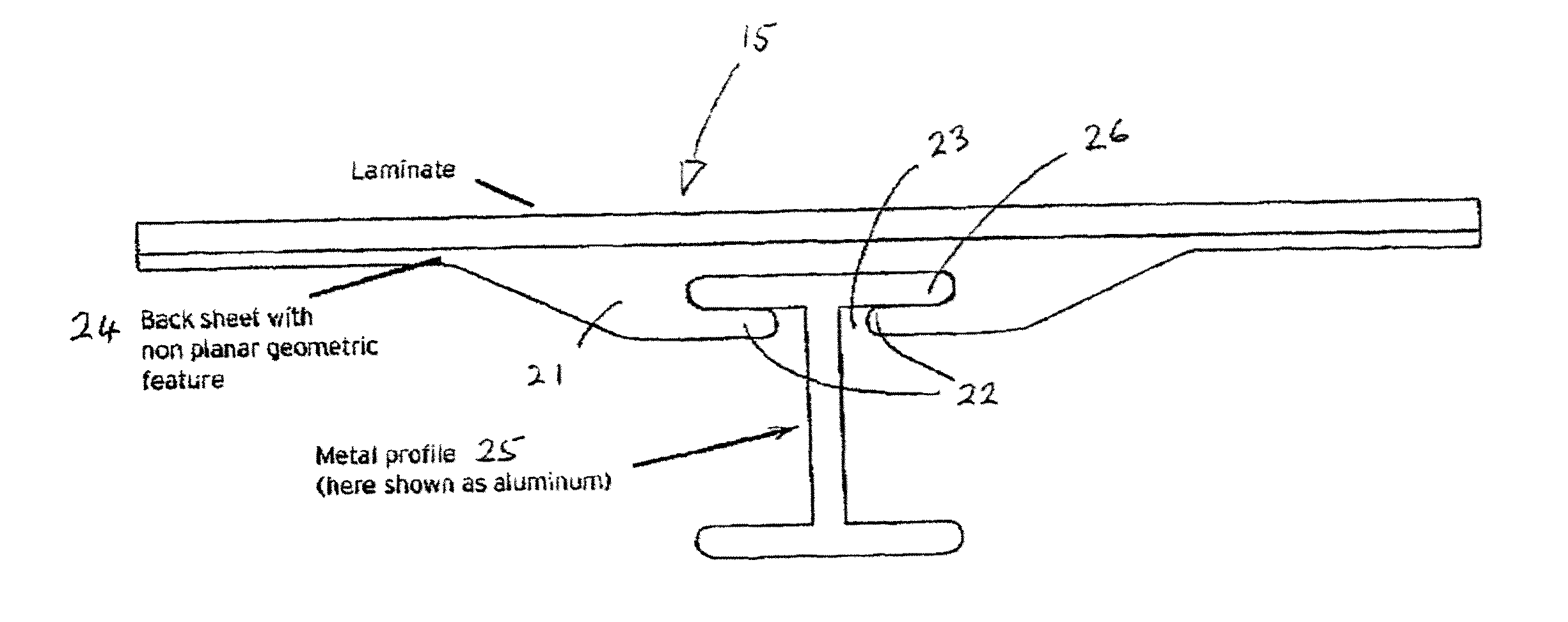
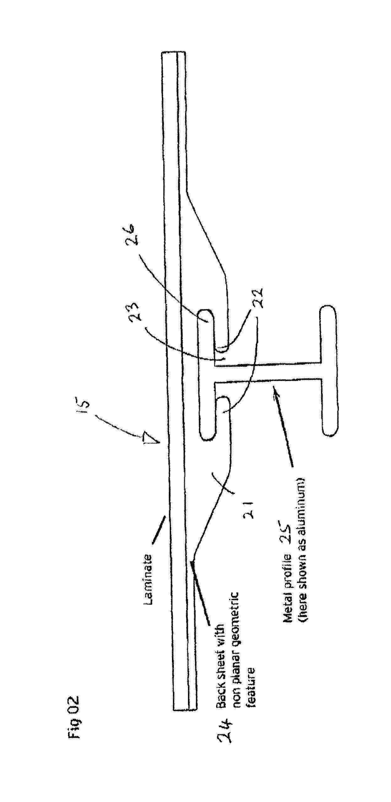
[0082]FIG. 2 shows the invention. The laminated panel 15 has a back sheet 24 which is formed integrally with an attachment feature 21. The feature 21 stands out slightly from the back sheet (e.g. by between 1 mm and 25 mm), and has two lips 22 arranged to limit access to a central slot 23 (recess). This figure shows a support formed as an aluminum ‘I’ beam 25. The upper flange 26 of the ‘I’ beam 25 fits into the slot 23. (The configuration of the slot 23 can be designed specifically to accept standard sized flanges 26.) It is important that the flange 26 fits securely into the slot 23. The ‘I’ beam 25 in this case forms part of a support structure (not shown but lying beneath the ‘I’ beam) for the panel 15. The attachment feature 21 permits easy on-site assembly of the panel 15 onto the support structure which may be a roof, tracker or ground mounted structure. Roofs may have flat or corrugated surfaces, tiles or shingles. Additional features may be added to prevent loss of the pane...

second embodiment

[0085]FIG. 3 shows the invention.

[0086]In this case the planar back sheet is wholly incorporated into the laminate 15A. An attachment feature 31 is joined to the back sheet 34 with an adhesive 37. The configuration of the attachment feature 31 is similar to the feature 21 shown in FIG. 2. Lips 32 limit access to a central slot 33, which on assembly fits around the upper flange 36 of an ‘I’ beam 35. Whilst an adhesive may be used to bond compatible polymers it also provides advantages in bonding polymers which may not be directly compatible for welding purposes.

[0087]FIGS. 4a and 4b show rear views (non-insolation side) of panels according to the invention.

[0088]FIG. 4a shows two attachment features (such as 31 in FIG. 3) bonded in spaced parallel relationship to the back sheet of a PV panel 15, and FIG. 4b shows four similar attachment features bonded to a similar panel. The cross sectional shapes of the attachment features and their relationship to the panel as a whole are shown cl...

third embodiment

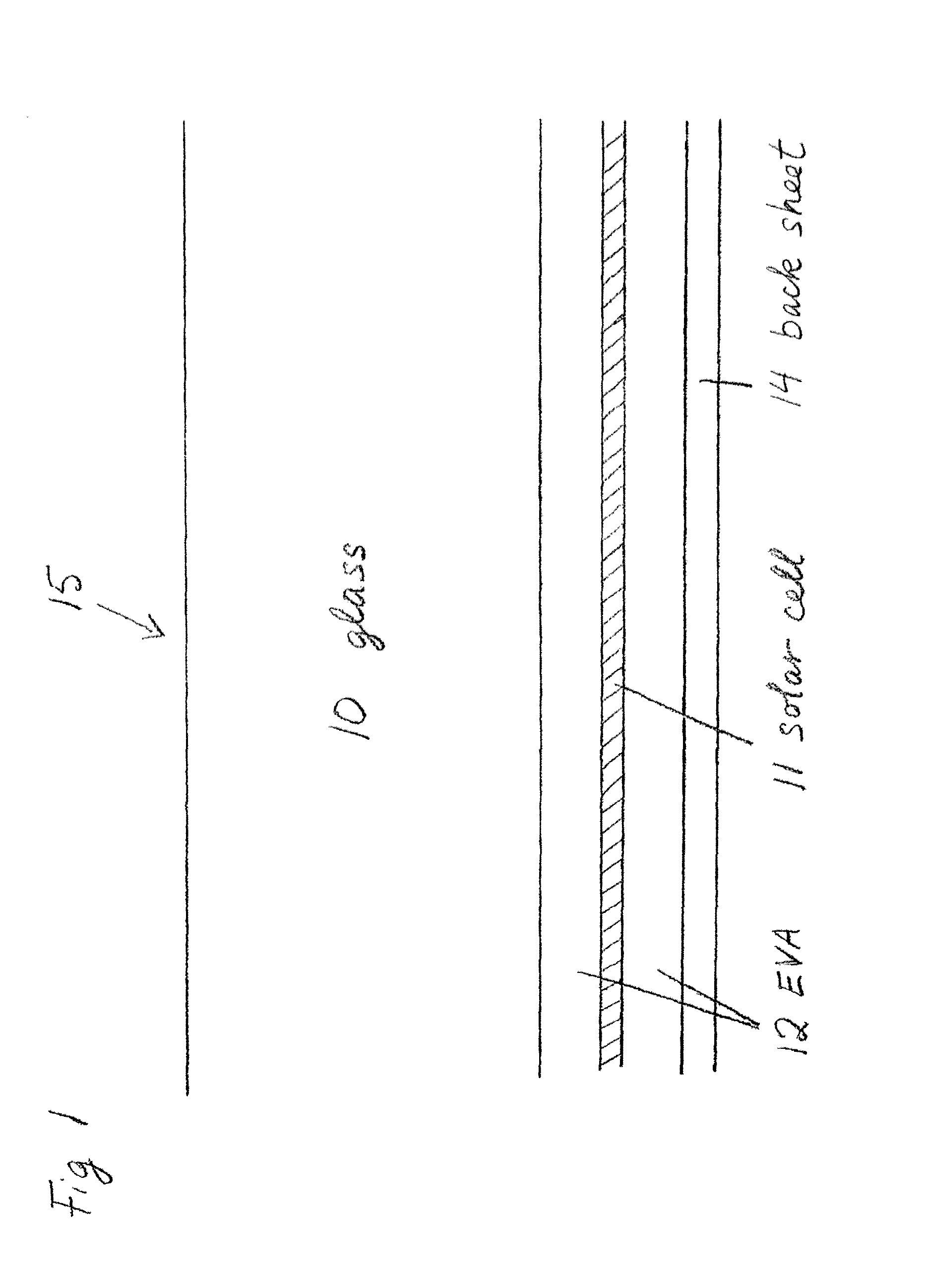
[0098]FIG. 9 shows the invention. A glass superstrate overlies a PV cell which in encapsulated in a layer of EVA. Back sheet 84 is laminated with the glass and EVA layers to form an integral laminate panel. An attachment feature 83 is bonded to the outer side of the back sheet with adhesive 86. In this case the attachment feature has opposed slots 87 in its outer surfaces, so that engagement can be effected by two inwardly facing opposed edges 88. The edges 88 are formed on an open ‘C’ profile steel support member 89. The edges are the opposed ends of the open profile, and the upper faces of that profile lie directly below portions of the attachment feature 83, so to give direct support to the laminate above the adhesive 86.

[0099]FIG. 10 shows a forth embodiment of the invention. This is similar to the third embodiment, except that the upper faces of the attachment feature 93 are welded directly to the back sheet 94 at a welded joint 96. As with the third embodiment, the edges 98 of...


PUM


Abstract

A method is provided of fabricating a photo voltaic generator panel (15) including a polymer back sheet (24) with at least one attachment feature (21) so as to provide means of attaching the panel to a structural support (25) upon subsequent installation. At least one polymer attachment feature (21) is applied to the outer side of the polymer back sheet of the panel during the manufacturing process for the panel whereby the attachment feature projects with respect to the back sheet. The application may be in conjunction with a lamination process, or subsequent to the lamination process, or as an integral part of the back sheet manufacturing process. The attachment feature is adapted to engage with a corresponding feature (26) or features to be found on a support structure (25) located at a site for the installation of the panel. The said at least one polymer attachment feature and said outer side of the polymer back sheet have a similar thermal expansion coefficient.

Description

FIELD OF THE INVENTION[0001]The invention relates to a photo voltaic (PV) panel facilitating effective installation and support for the PV panel or a series of such panels.BACKGROUND OF THE INVENTION[0002]In the production and fitting of solar panels to roofs of buildings, tracker structures or fixed ground mounting structures, transport and final installation costs are significant. By the nature of their characteristics, solar panels consist of thin laminates, the rigidity of which is critical to their performance and durability under various weather conditions in different geographical regions of the world.[0003]Some PV solar panels known today are planar laminated products. They consist of a front glass “superstrate”, a multiplicity of solar cells encapsulated by a polymer and a back sheet. These are bonded into one planar panel by a lamination process. Some laminates are supported by an aluminum frame. For installation of such a PV panel, this frame may be mounted on an underlyi...

Claims


Application Information

Patent Timeline
IPC IPC(8): H01L31/042H01L31/18
CPCF24J2/4636F24J2/5205F24J2/5249F24J2/5254F24J2002/467F24J2002/4676H02S20/00H01L31/048Y02E10/50Y02B10/12Y02E10/47H01L31/18H02S20/23H01L31/0422H02S20/10F24S25/615F24S40/80F24S25/632F24S2025/601F24S25/33F24S2025/6007Y02B10/10
Inventor BJORNEKLETT, BORGEHOLM, OYSTEINSAUAR, ERIK
Owner REC SOLAR
Why Eureka
Try Eureka