Emergency escape device
- Summary
- Abstract
- Description
- Claims
- Application Information
AI Technical Summary
Benefits of technology
Problems solved by technology
Method used
Image

Examples
first embodiment
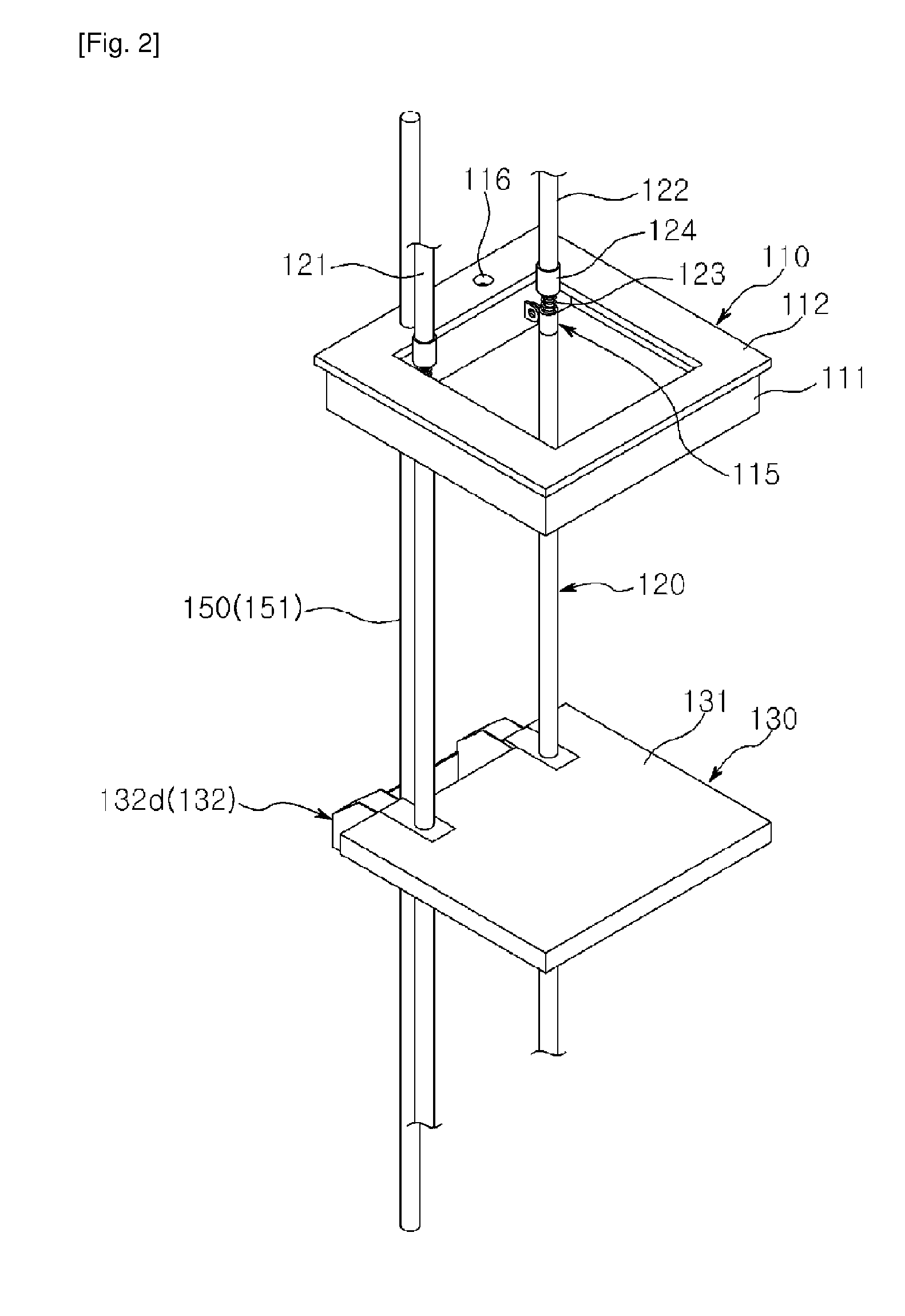
[0062]In the emergency escape device according to the present invention, the large gear 143 of the slowing unit 140 having the pulley 142 is rotated both when the descending unit 130 descends and when the descending unit 130 ascends. A ratchet mechanism (not shown) may be provided between the large gear 143 and the pulley 142 so that only the pulley 142 can rotate when the descending unit 130 is moved up along the guide frames 121 and 122 by means of the returning unit 150. This enables the descending unit 130 to rapidly come back to the original position.
[0063]The emergency escape device according to the first embodiment of the present invention may further include a lighting unit (not shown) for lighting the fire evacuation area so that an evacuee can safely escape even in the event of electric outage. The lighting unit preferably includes a lamp arranged in the upper portion of each of the guide frames 121 and 122 and a power supply for supplying an electric current to the lamp. ...
second embodiment
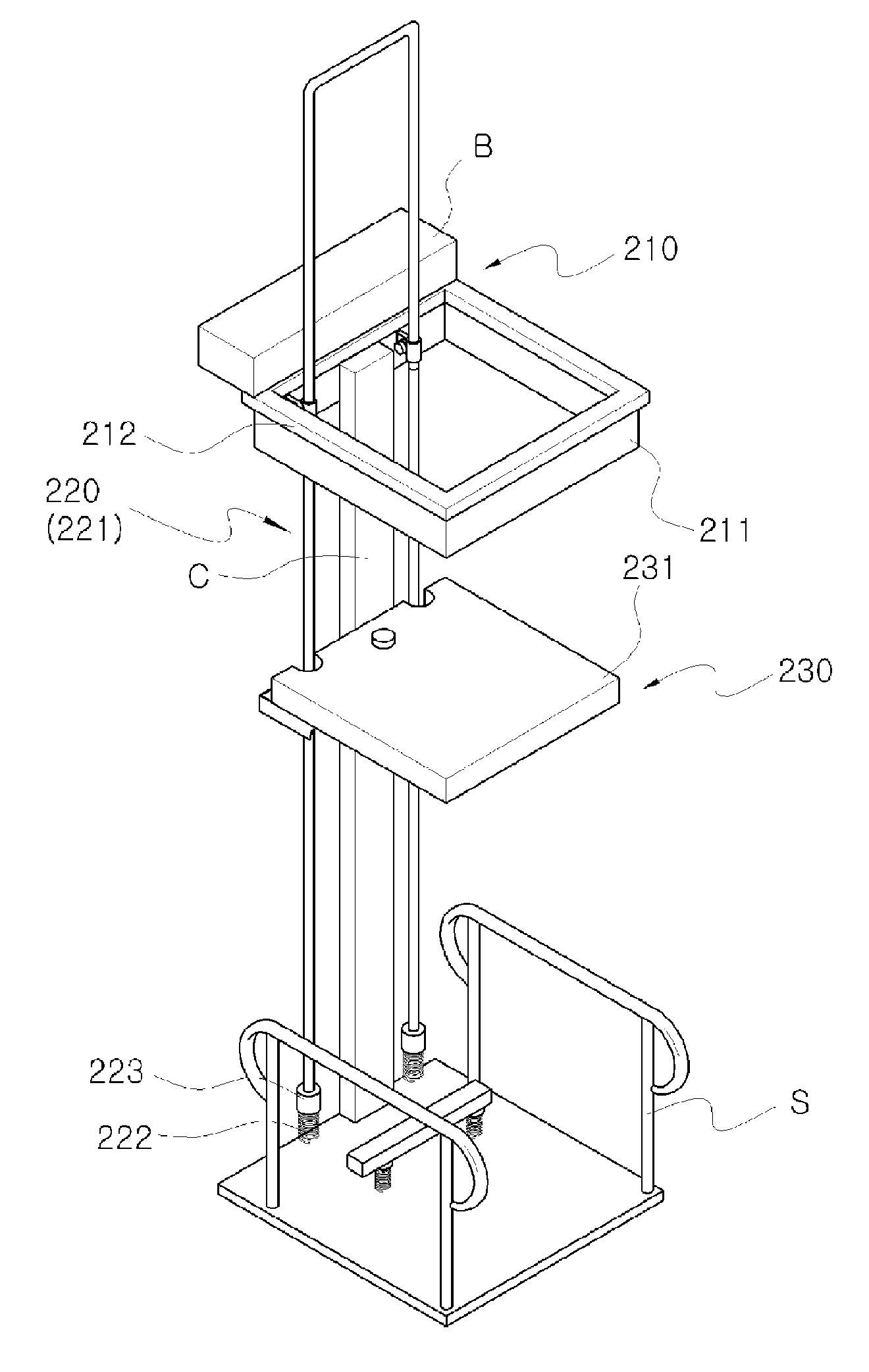
[0133]In the emergency escape device according to the present invention, the large gear 243 of the slowing unit 240 is rotated both when the descending unit 230 descends and when the descending unit 230 ascends. A ratchet mechanism (not shown) may be provided in the large gear 243 so that the descending unit 230 can rapidly come back to the original position.
[0134]Next, description will be made on the operation of the emergency escape device according to the second embodiment of the present invention.
[0135]FIGS. 18 and 19 are views illustrating an emergency escape operation performed by the emergency escape device shown in FIG. 15.
[0136]As shown in FIGS. 18 and 19, the escape hole cap 210 is installed in the escape hole P formed on the floor surface of a specified story. Then, the guide frames 221 of the guide unit 220 are fixed to the insertion body 211 of the escape hole cap 210. Thereafter, the slowing unit 240 and the returning unit 250 are installed in the module box B arranged...
PUM
 Abstract
Description
Claims
Application Information
 - Generate Ideas
- Intellectual Property
- Life Sciences
- Materials
- Tech Scout
- Unparalleled Data Quality
- Higher Quality Content
- 60% Fewer Hallucinations
Browse by: Latest US Patents, China's latest patents, Technical Efficacy Thesaurus, Application Domain, Technology Topic, Popular Technical Reports.
© 2025 PatSnap. All rights reserved.Legal|Privacy policy|Modern Slavery Act Transparency Statement|Sitemap|About US| Contact US: help@patsnap.com