Power generator

a power generator and vibration energy technology, applied in piezoelectric/electrostrictive/magnetostrictive devices, piezoelectric/electrostriction/magnetostriction machines, electrical apparatus, etc., can solve the problems of low current output, low power output, and limited use of piezoelectric benders for vibration energy harvesters. , to achieve the effect of reducing the degree of stiffness and resonance tuning, reducing the cost, and reducing the cos

Inactive Publication Date: 2013-08-15
GENZIKO
View PDF17 Cites 46 Cited by
  • Summary
  • Abstract
  • Description
  • Claims
  • Application Information

AI Technical Summary

Benefits of technology

[0039]U.S. Pat. Appl. No. 2008 / 0246367 to Fochtman uses a conventional bender, whose surface has been modified with ridges, grooves, or holes, in order to modify the sheet stiffness and the device resonance. Changing the surface structure of the piezoelectric allows a modest degree of tuning of the stiffness and resonance of conventional benders. However, this modification would be expensive and could negatively impact reliability. Other techniques such as mass-springs would appear to be a lower cost solution.

Problems solved by technology

However, the use of conventional piezoelectric benders for vibration energy harvesters has been limited due to their low energy output, high vibrational frequency requirement, and narrow frequency bandwidth.
Currently, micro-electro-mechanical systems (MEMS) and conventional vibrational energy harvesters develop microwatt and milliwatt power levels, respectively, limiting their usage to powering MEMS sensors, ultralow power wireless sensors, or ultralow power electronic devices.
Whereas, prior art piezoelectric-based power generators have adequate voltage output (high g31), unfortunately they have suffered from low current output (d31) and thusly low power output (g31*d31) (see piezoelectricity standard ANSI / IEEE Std. 176-1987).
As shown herein in FIG. 3, these prior art generators have low energy output except at high vibrational amplitudes, narrow frequency bandwidth, and low efficiency.
However, because these conventional bimorphs have low efficiency, when they are connected in parallel, this causes problems with one element discharging into the next.
Therefore, each element must be wired or isolated which is complicated.
U.S. Pat. No. 7,293,411 to Fitch uses altering liquid distribution to improve the tuning of conventional bimorphs which have inherently low efficiency, wherein the tuning “tries” to maximize the output which can be accomplished either mechanically (per Fitch) or electrically.
However, this will only marginally improve the bandwidth or efficiency.
This concept utilizes conventional circular bimorphs which have inherently low efficiency.
The film which bends similar to conventional bimorphs has inherently low efficiency.
This concept utilizes conventional cantilever benders, which have inherently low efficiency.
In addition, higher motion is provided, though the strength of the bender will limit the amount of motion amplification which can be utilized.
However, this structure can only operate in a low efficiency mode.
Fibers such as these have been proposed many times, but are thought to have never been fabricated successfully.
This, however, creates a difficulty that each material has a different sign and that cancels the other unless harvested separately.
In addition, due to its use of coils and permanent magnets, the magnetostrictive component will suffer from energy density.
Therefore, the struck piezoelectric will have very low energy generation.
In addition, the ceramic could not be struck quickly enough to generate much power.
Tanielian does not address the problem with low output from the harvester itself.
As such, it has been shown that little to no improvement in energy density has been realized.
However, strikes or impacts produce high voltage, but low current and power, as is utilized in gas igniters.
Also, the impact can seriously degrade and / or damage the material over time.
Though the efficiency is higher using thickness mode, it suffers by being transformed.
However, this modification would be expensive and could negatively impact reliability.

Method used


Image

  • Power generator
  • Power generator
  • Power generator

Examples


Embodiment Construction

[0062]It is to be understood that the invention may assume various alternative orientations and step sequences, except where expressly specified to the contrary. It is also to be understood that the specific devices and processes illustrated in the attached drawings, and described in the following specification are simply exemplary embodiments of the inventive concepts defined in the appended claims. Hence, specific dimensions, directions or other physical characteristics relating to the embodiments disclosed are not to be considered as limiting, unless the claims expressly state otherwise.

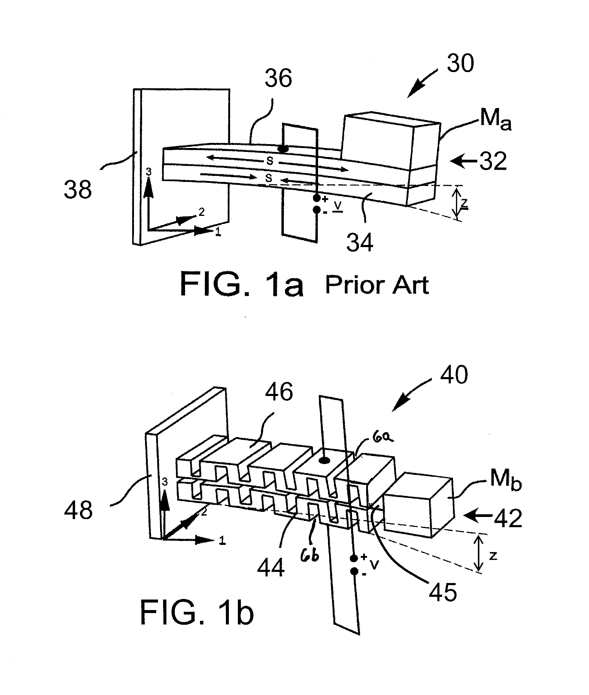
[0063]As mentioned above, FIG. 1a illustrates a conventional monolithic bimorph energy harvester 30 that comprises a stiff cantilever beam 32 that is made up of two elements 34, 36, with a mass Ma. The cantilever beam 32 is mechanically affixed to a rigid wall 38.

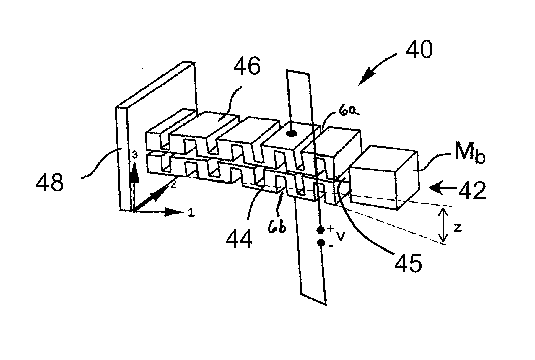
[0064]The present invention, however, is a serpentine energy harvester that comprises at least one serpentine layer, which comprises a p...


PUM

PropertyMeasurementUnit
piezoelectricaaaaaaaaaa
electrically conductiveaaaaaaaaaa
massaaaaaaaaaa

Abstract

An electrical power generator has one or more serpentine elements that are made of a poled piezoelectric or electrostrictive ceramic, one or more electrically conductive shims or foils and at least two electrically conductive electrode coatings on the serpentine element. The conductive electrodes are further electrically connected to an electrical load or energy storage device or both, and the serpentine element is mechanically affixed to a source of compression or vibration or both.

Description

RELATED APPLICATION[0001]This application claims the benefit under 35 U.S.C. §119(e) of U.S. Provisional Patent Application Ser. No. 61 / 597,361, filed Feb. 10, 2012, which is incorporated by reference herein in its entirety.GOVERNMENT CONTRACT INFORMATION[0002]The Government of the United States of America may have certain rights in this invention pursuant to Contract No. IP0839600, awarded by or for the National Science Foundation.FIELD OF THE INVENTION[0003]The present invention relates to a vibration energy harvester being utilized as a power generator. More particularly, the present invention relates to a vibration energy harvester, in the form of a poled piezoelectric or electrostrictive ceramic body serpentine element, being utilized as a power generator.BACKGROUND OF THE INVENTION[0004]By using wasted and often unwanted vibrational energy, small-scale vibrational energy harvesters have the potential of powering embedded, remote, and portable low power electronic circuits, sen...

Claims


Application Information

Patent Timeline
Patent Type & Authority Applications(United States)
IPC IPC(8): H02N2/18
CPCH01L41/1134H02N2/186H02N2/188H01L41/1136H10N30/304H10N30/306
Inventor NEAR, CRAIG D.
Owner GENZIKO
Why Eureka
Try Eureka