
Mach-zehnder optical modulator using a balanced coplanar stripline with lateral ground planes

a coplanar stripline and optical modulator technology, applied in non-linear optics, instruments, optics, etc., can solve the problems of tsuzuki not teaching how to implement differential electrical drive, the design of klein becomes apparent, and the disadvantage of losing a large fraction of the electrical power supplied by the rf driver

Active Publication Date: 2013-08-15
CIENA
View PDF1 Cites 51 Cited by
  • Summary
  • Abstract
  • Description
  • Claims
  • Application Information

AI Technical Summary

Benefits of technology

The invention is a special light-based device called a Mach-Zehnder optical modulator. This device uses a special design with two signal electrodes that run along the center of the device. These electrodes are positioned next to the optical waveguides in a way that they create a push-pull effect. The device also has two ground planes that run parallel to the signal electrodes, but are positioned outward from them. The technical effect of this design is that it allows for greater control and efficiency in the modulation of optical signals.

Problems solved by technology

This configuration has the disadvantage of losing a large fraction of the electrical power supplied by the RF driver 41.
A further disadvantage of the design of Klein becomes apparent when multiple modulators are monolithically integrated in close proximity to each other on a single chip.
These voltages and currents couple strongly to the transmission line conductors of the neighboring modulators in a disadvantageous phenomenon known as crosstalk.
Tsuzuki does not teach how to implement differential electrical drive with a series push-pull Mach-Zehnder optical modulator.
It should be noted that the Walker solution cannot use both S+ and S− signals from a differential driver, thereby losing a large fraction of the electrical power, and suffers from poor modulation performance due to the open-terminated ground conductor.
There is no common conducting backplane under the optical waveguides to place the electrode capacitance in series, so it does not benefit from the halving of the capacitance derived from the series push-pull configuration.
Thus far, none of the prior-art has presented a Mach-Zehnder modulator capable of combining these advantages.

Method used


Image

  • Mach-zehnder optical modulator using a balanced coplanar stripline with lateral ground planes
  • Mach-zehnder optical modulator using a balanced coplanar stripline with lateral ground planes
  • Mach-zehnder optical modulator using a balanced coplanar stripline with lateral ground planes

Examples


Embodiment Construction

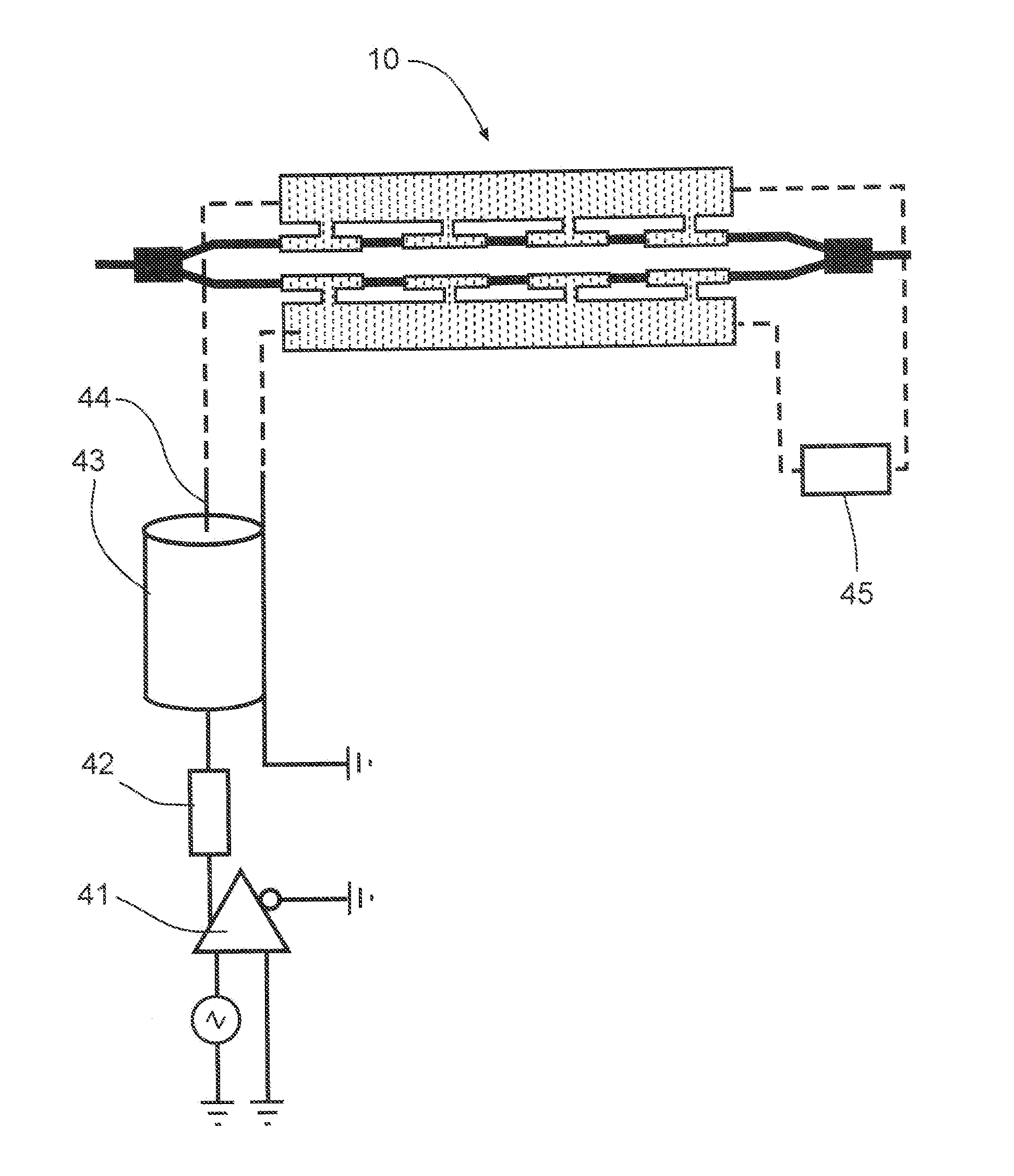
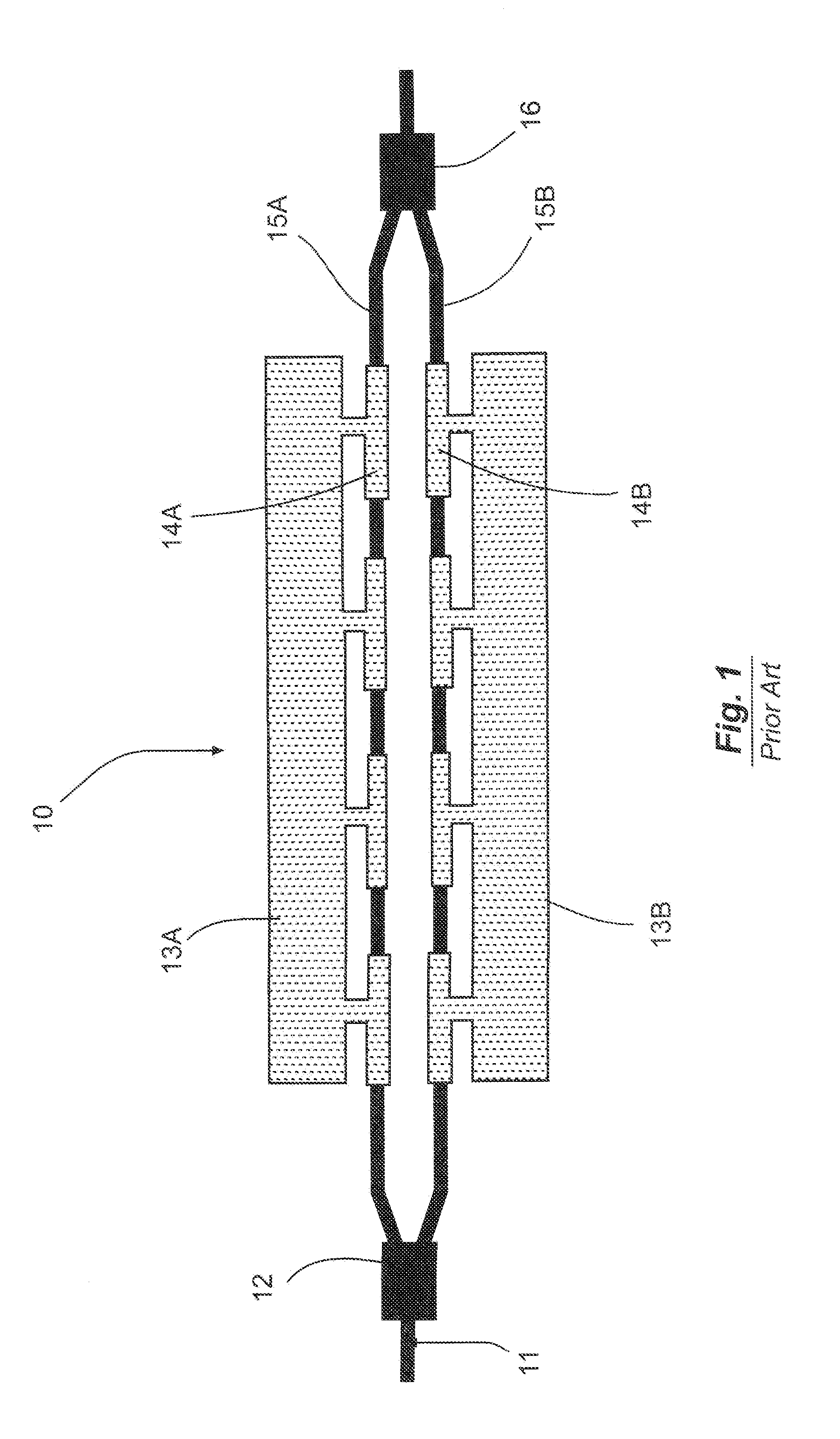
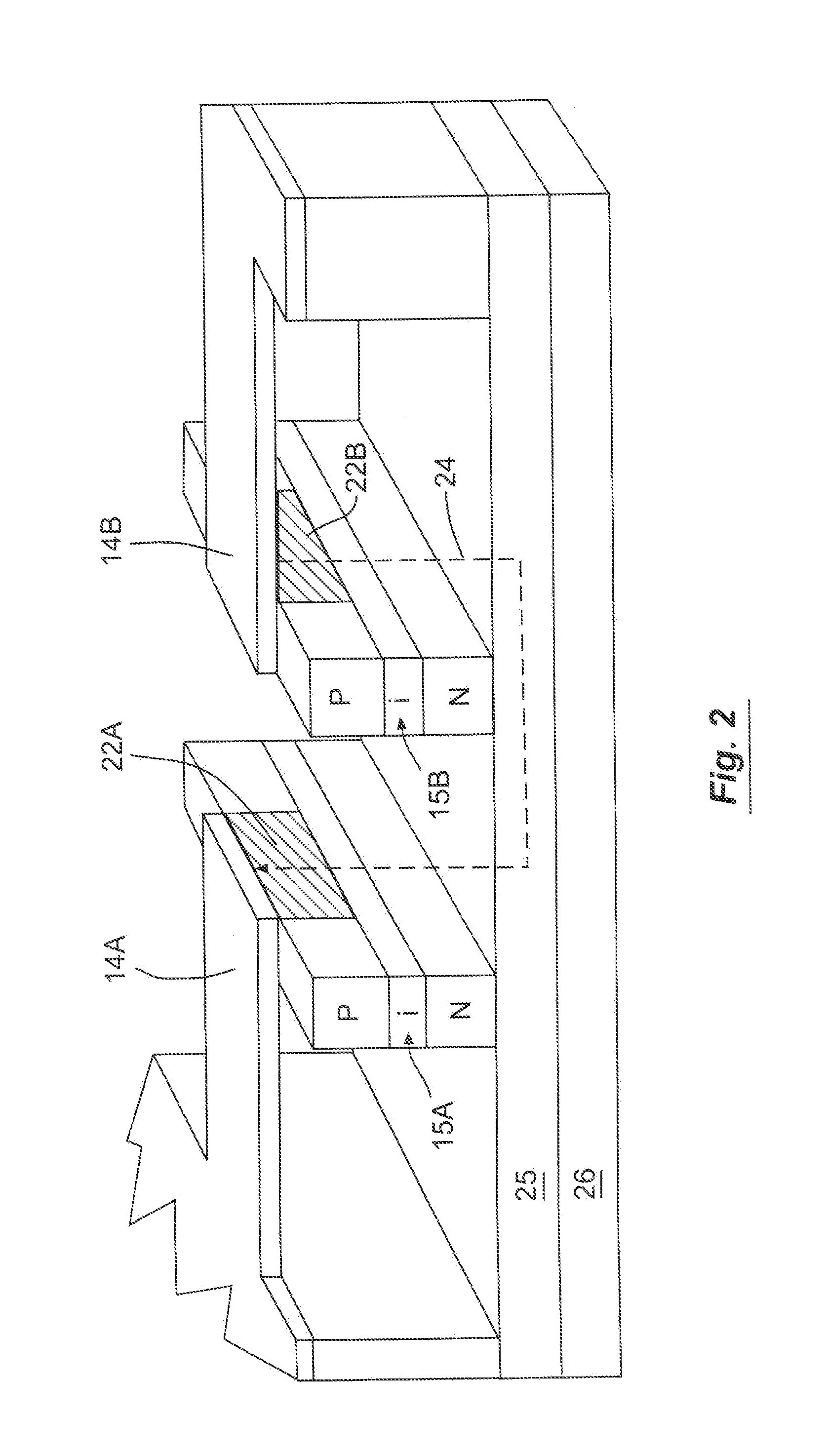
[0030]FIG. 7 is a schematic of a Mach-Zehnder optical modulator embodying the present invention. FIG. 7 also includes the differential driver circuit 61 and a transmission line converter section 76 that is the subject of the Applicant's U.S. patent application Ser. No. 13 / 722,400, entitled “Electronic Waveguide Transmission Device For Use With A Mach-Zehnder Optical Modulator,” filed on Dec. 20, 2012. This patent application is hereby incorporated by reference. The optical configuration of the device generally follows that of a conventional Mach-Zehnder optical modulator. A beamsplitter 12 divides the input optical signal into two optical paths that propagate in parallel along two optical waveguides 15A, 15B. A series push-pull traveling wave electrode is used to modulate the relative phase of optical signals along these optical waveguides. The beams are then recombined by an optical recombining element 16 at the output. Changing the electric field on the phase-modulating paths by m...


PUM


Abstract

A Mach-Zehnder optical modulator with a series push-pull traveling wave electrode uses a balanced coplanar stripline with lateral ground planes. Two signal electrodes extend along the center of the optical modulator adjacent and parallel to the optical waveguides in a series push-pull configuration. The ground planes run parallel to the signal electrodes, but are spaced laterally outward from the signal electrodes.

Description

RELATED APPLICATION[0001]The present application is based on and claims priority to the Applicant's U.S. Provisional Patent Application 61 / 598,994, entitled “Mach-Zehnder Optical Modulator Using A Balanced Coplanar Stripline With Lateral Ground Planes,” filed on Feb. 15, 2012.BACKGROUND OF THE INVENTION[0002]1. Field of the Invention[0003]The present invention relates generally to the field of Mach-Zehnder optical modulators. More specifically, the present invention discloses a Mach-Zehnder optical modulator using a balanced coplanar stripline with lateral ground planes.[0004]2. Background of the Invention[0005]Mach-Zehnder optical modulators have been employed for many years in the field of optical communications to accept modulated data in electrical (e.g., radio frequency) format and transfer the data onto an optical carrier. In a Mach-Zehnder optical modulator as generally shown in FIG. 1, a beamsplitter 12 divides the laser light from the input optical waveguide 11 into two pat...

Claims


Application Information

Patent Timeline
IPC IPC(8): G02F1/225G02F1/01
CPCG02F2201/126G02F1/011G02F1/225G02F2201/127
Inventor PROSYK, KELVIN
Owner CIENA
Learn More