Control apparatus for vehicles, operating machines or the like
a technology for controlling apparatus and vehicles, applied in mechanical apparatus, transportation and packaging, braking systems, etc., can solve problems such as heavy load on control means, damage to vehicles, and user effor
Active Publication Date: 2013-08-15
SAFIM
View PDF7 Cites 0 Cited by
- Summary
- Abstract
- Description
- Claims
- Application Information
AI Technical Summary
Benefits of technology
The present invention aims to offer a control system for vehicles, machines, and other such devices. The system should overcome the shortcomings of the current market by controlling the transmission during the initial phase of the control means' stroke while maintaining a long stroke and reducing displacement. This would make it easier for the user to operate the device. Furthermore, the invention aims to provide a simple, cost-effective, and user-friendly solution to control vehicles, machines, and other such devices.
Problems solved by technology
In fact, such solution necessarily requires that the stroke of the control means be restricted in order to avoid the pressure inside the pump-brake from rising too far before the transmission has been completely disengaged with a consequent overheating effect that could cause damage to the vehicle.
Because the braking stage takes place during a reduced stroke of the control means, the pump-brake piston must have a large diameter, which consequently results in a heavy load on the control means and therefore considerable effort on the part of the user.
In fact, the positioning of the control device along the delivery line of the pump-brake results in the transmission only being reduced after the braking action has begun.
Method used
View moreImage
Smart ImageViewing Examples
Examples
first embodiment
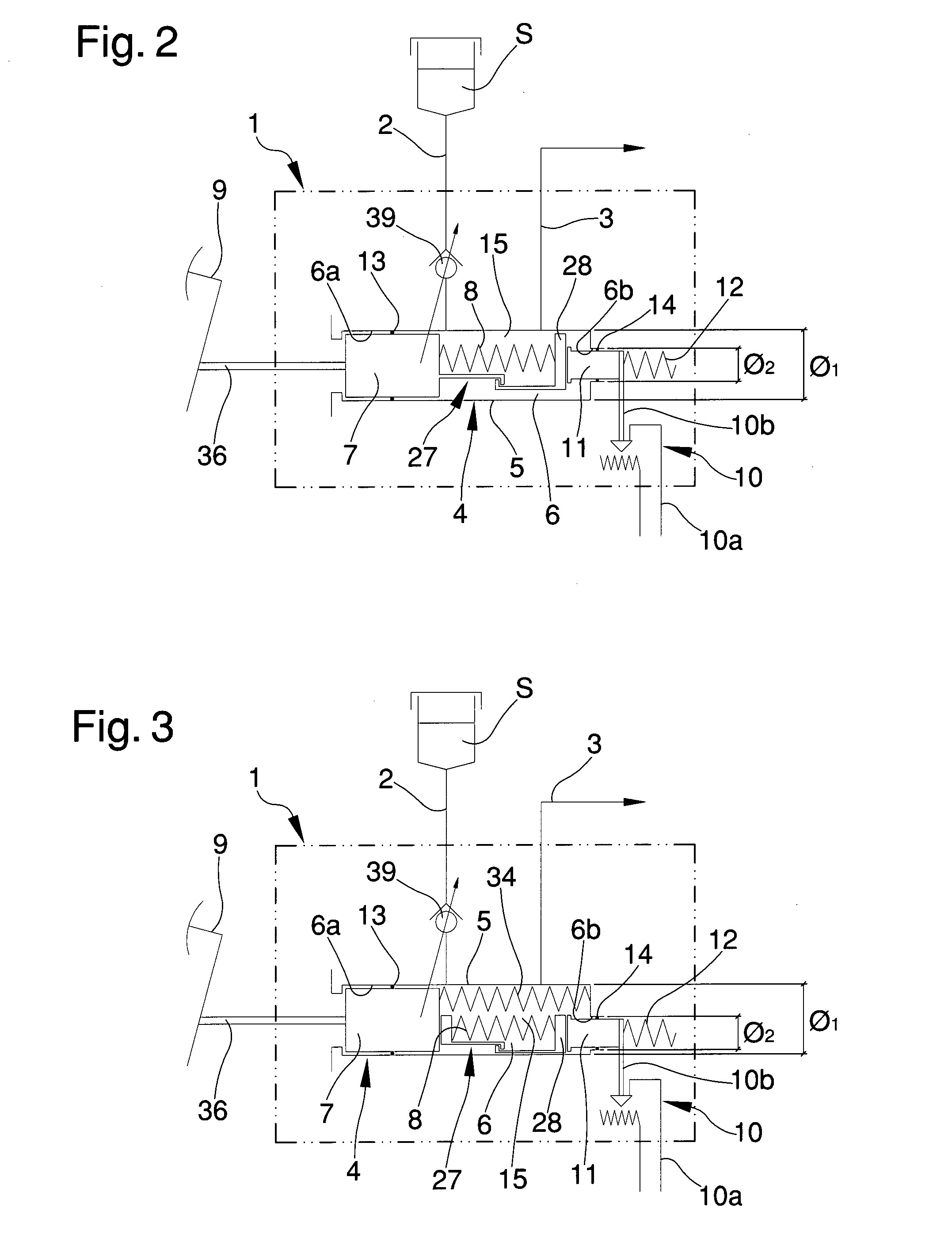
[0038]FIG. 2 is a hydraulic diagram of the control apparatus according to the invention in a first embodiment;
second embodiment
[0039]FIG. 3 is a hydraulic diagram of the control apparatus according to the invention in a second embodiment;
third embodiment
[0040]FIG. 4 is a hydraulic diagram of the control apparatus according to the invention in a third embodiment;
Login to View More PUM
 Abstract
The control apparatus includes feeding and delivery lines of the operating fluid, a pump-brake having a containment body which defines a sliding chamber and a main piston housed sliding inside the chamber, a control element controlling the movement of the main piston which can be operated by an operator, a control device for controlling the motion transmission of a vehicle or of an operating machine including a fixed part and a moving part suitable for cooperating together, wherein the moving part is suitable for moving through the operation of the control element and includes an auxiliary piston moving between a reference position and at least a detection position and mechanically connected to the moving part to move it with respect to the fixed part during its movement between the reference position and the detection position, the auxiliary piston moving towards the detection position through the movement of the main piston.
Description
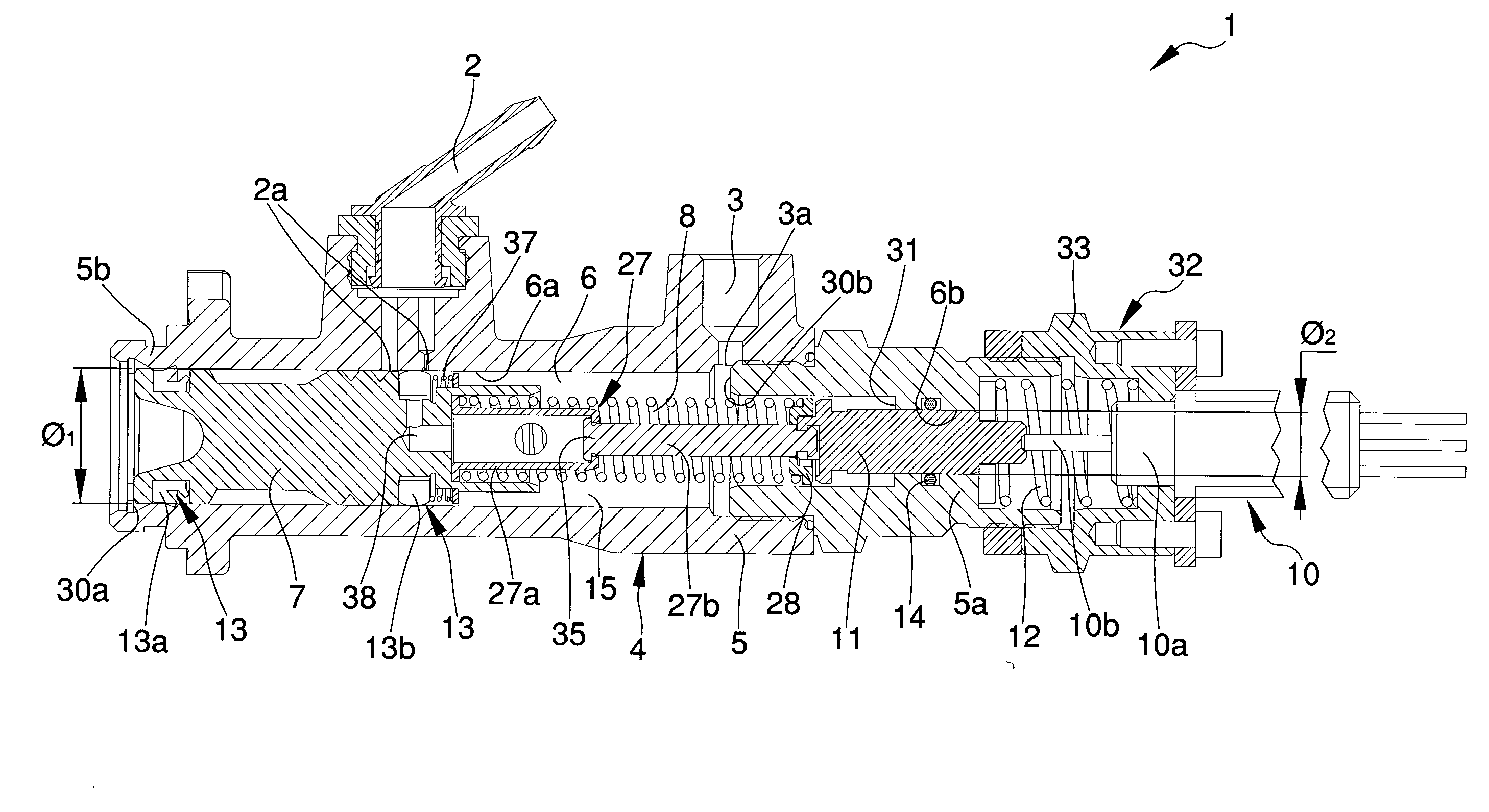
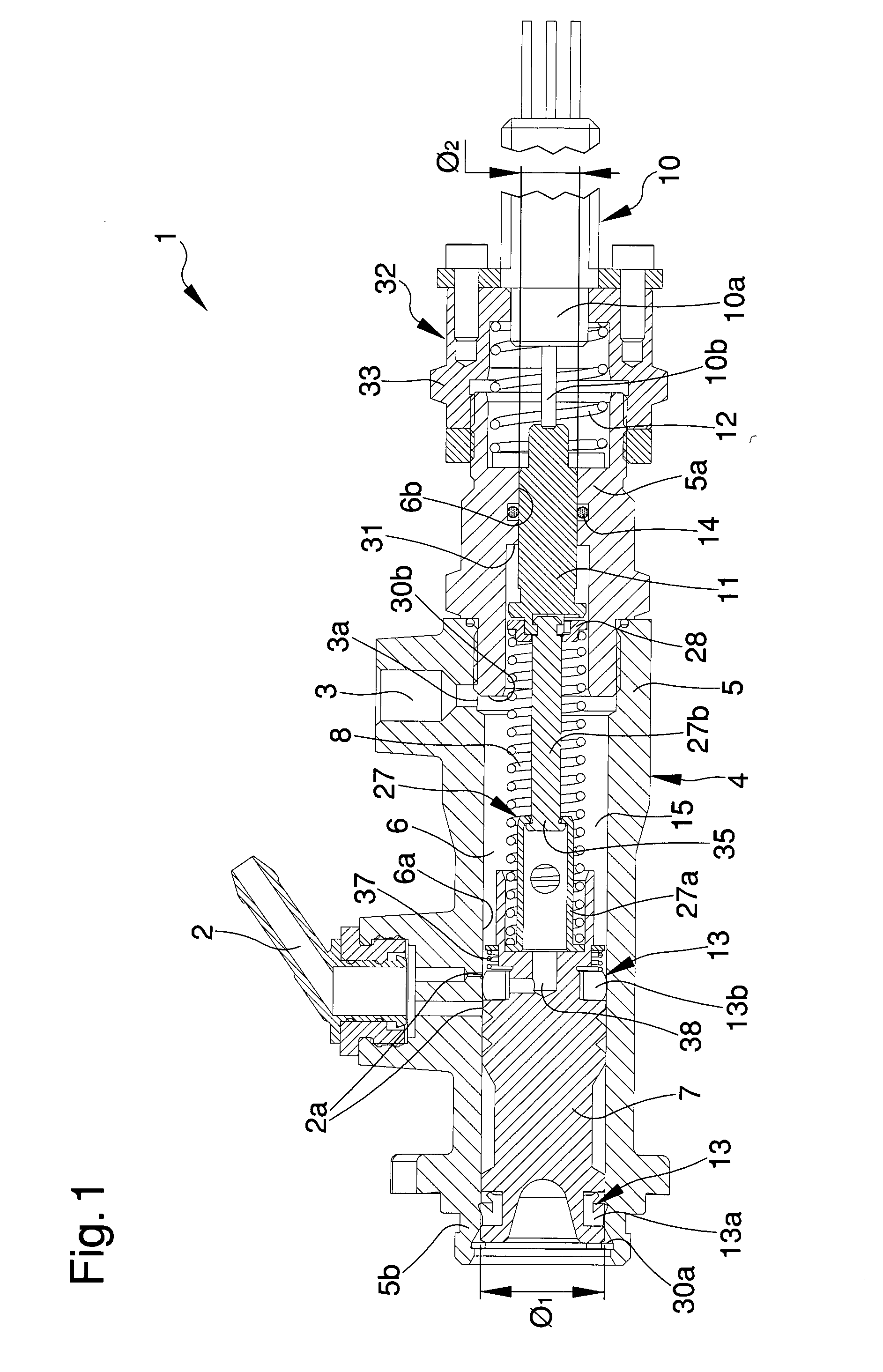
TECHNICAL FIELD[0001]The present invention relates to a control apparatus for vehicles, operating machines or the like.BACKGROUND ART[0002]Many operating machines, such as fork-lift trucks, shovels and the like offer the possibility of electronically controlling the transmission of movement from the motor to the wheels.[0003]As technicians in the sector know, these operating machines have a function known as “inching” which allows the operator to reduce and control the speed of the operating machine by means of the brake pedal, thus changing the transmission conditions so as to adjust the traction.[0004]During the first part of the brake pedal stroke, the “inching” function allows reducing the traction without operating the brakes.[0005]More in particular, during the first part of the pedal stroke, the operator modulates the speed of the operating machine by adjusting the movement transmission speed, while in the second part of the stroke, the further movement of the pedal causes di...
Claims
Login to View More Application Information
Patent Timeline
 IPC IPC(8): F15B15/08
CPCB60T11/165F15B15/08B60T17/22
Inventor MAMEI, ENRICO
Owner SAFIM
Features
- R&D
- Intellectual Property
- Life Sciences
- Materials
- Tech Scout
- Unparalleled Data Quality
- Higher Quality Content
- 60% Fewer Hallucinations
Learn More Browse by: Latest US Patents, China's latest patents, Technical Efficacy Thesaurus, Application Domain, Technology Topic, Popular Technical Reports.
© 2025 PatSnap. All rights reserved.Legal|Privacy policy|Modern Slavery Act Transparency Statement|Sitemap|About US| Contact US: help@patsnap.com


