Fuel Cell System

Inactive Publication Date: 2013-08-15
DAIMLER AG
View PDF2 Cites 8 Cited by
  • Summary
  • Abstract
  • Description
  • Claims
  • Application Information

AI Technical Summary

Benefits of technology

[0007]Exemplary embodiments of the present invention avoid the above-mentioned disadvantages and to create a fuel cell system that enables a secure and reliable operation simply and efficiently, without the efficiency of the fuel cell system being compromised due to too high a water input into the cathode chamber.
[0008]According to exemplary embodiments of the present invention, a further water separator is thus provided, which is arranged in the supply line. In a different way from the constructions depicted in the above prior art, the water separator serves to separate water inserted from the supply to the cathode chamber of the fuel cell via the drain line of the water separator from the anode circuit. This water can then be discharged in a targeted manner, while the gases inserted into the region of the supply line, together with the water, can flow, in a completely separate manner from this water, into the cathode chamber of the fuel cell. The excess hydrogen contained therein can then abreact in the region of the electrocatalysts in order to avoid such hydrogen emissions from the fuel cell system. Using the further water separator in the supply line upstream of the cathode chamber has the essential advantage that, independent of the current operating status of the system and independent of the amount of supply to the system, even when the system is operative, the water and anode exhaust gas can be discharged. The strategy for discharging anode exhaust gas and water can also be carried out completely independently from the operative status of the fuel cell, in order to always guarantee the best possible hydrogen concentration in the region of the anode circuit.
[0009]It is only in situations where no oxygen is conveyed to the cathode chamber, so for example in a correspondingly designed stop operation of the fuel cell system, if this is operated as start/stop, that discharging water and gas should be dispensed with, since there is no oxygen available to convert the inserted hydrogen correspondingly in the region of the electrocatalysts of the cathode chamber. However, in all operative status in which there is at least a low level of supply flow flowing to the cathode chamber of the fuel cell, water and gas discharge can be carried out, since the amount of hydrogen being discharged is so low that even a very low supply flow is sufficient for avoiding hydrogen emissions.
[0010]In an advantageous development of the fuel cell system according to the invention, the further water separator can be connected to an exhaust line of the cathode chamber by a water delivery line. The water is inserted into the region of an exhaust line of the cathode chamber in a relatively direct route. Since a large portion of the product water present in the fuel cell is already contained in t

Problems solved by technology

The disadvantage of the construction described, which is also described in a similar fashion in FIG. 2 of U.S. Patent Publication No.
This can lead to punctiform voltage drops or to voltage drops in the region of individual cells.
Thus, with respect to operational stra

Method used


Image

  • Fuel Cell System
  • Fuel Cell System

Examples


Embodiment Construction

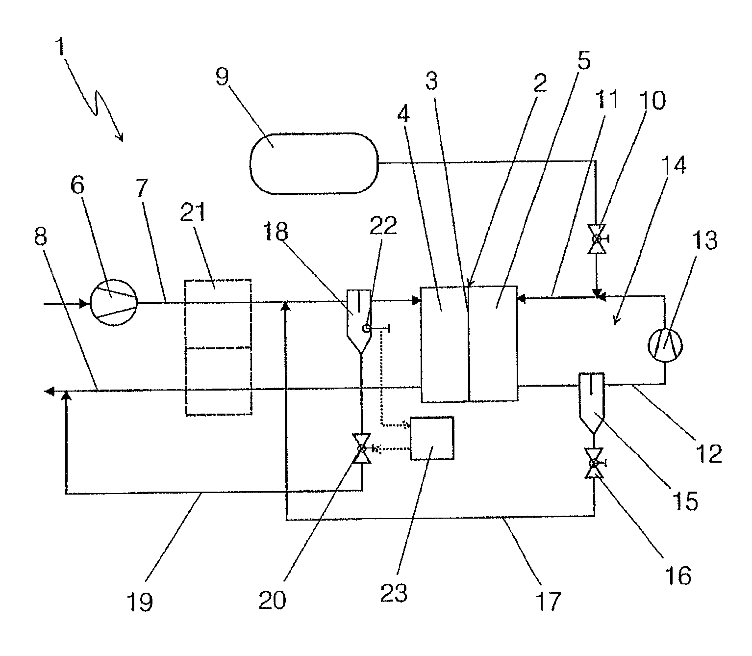
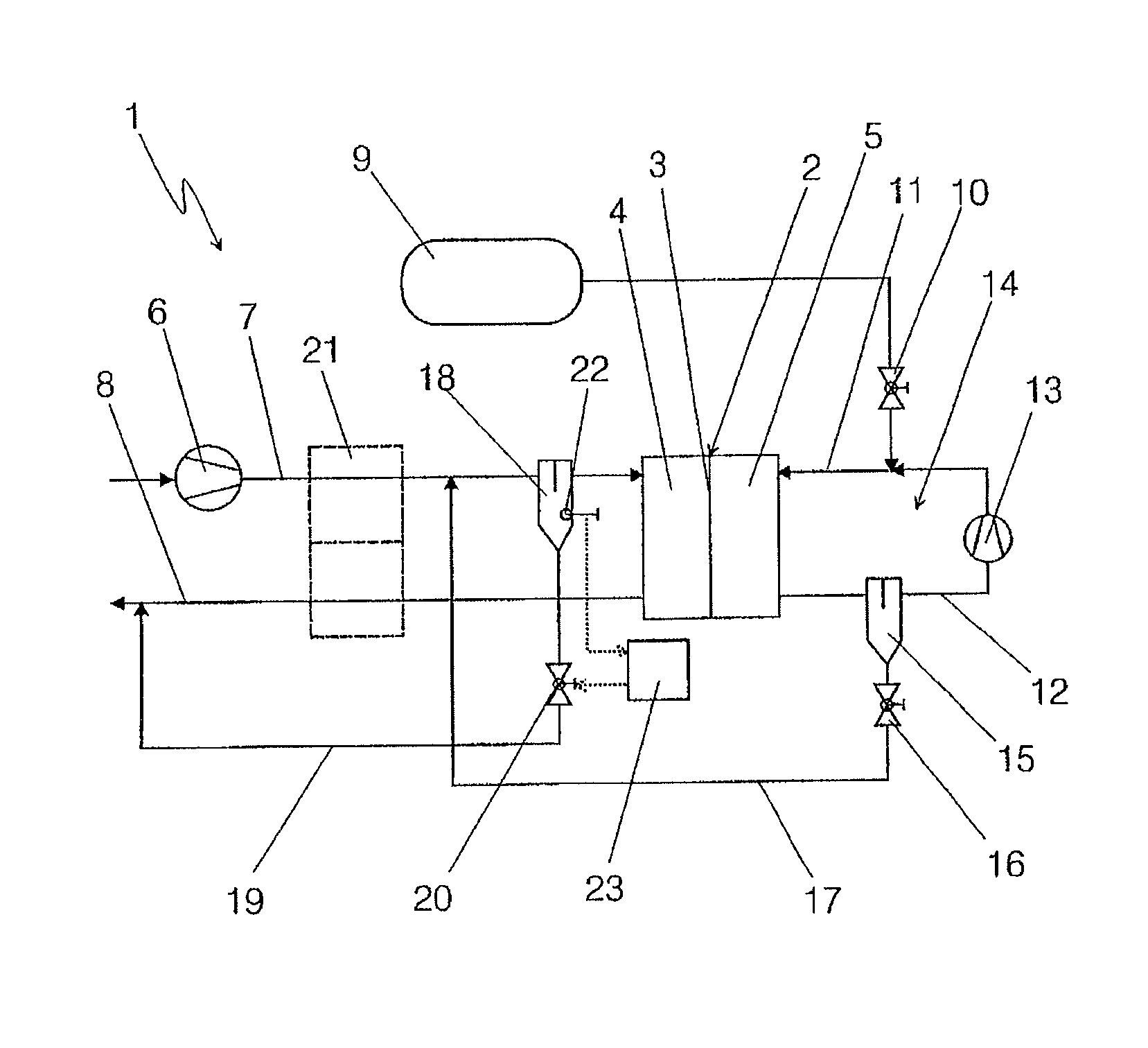
[0014]A fuel cell system 1 is to be identified in the FIGURE, which can ideally be used to provide electrical operating energy in a vehicle. It comprises a fuel cell 2, which is constructed, for example, as a sequence of individual cells. Here, the individual cells are preferably embodied with PEM technology and have a membrane 3, which separates a cathode chamber 4 from an anode chamber 5 of the fuel cell 2. Air is conducted into the cathode chamber 4 as oxygen delivery via an air conveyance device 6. This arrives at the region of the cathode chamber 4 via a supply line 7 and flows back via an exhaust line 8 out of the cathode chamber 4, depleted of oxygen. The exhaust air can then enter the atmosphere or, if desired, flow via suitable burners, turbines or suchlike beforehand, as is known in itself from the general prior art.

[0015]Hydrogen is conducted from a compressed gas storage unit 9 to the anode chamber 5 of the fuel cell 2 and arrives at the region of the anode chamber 5 via...


PUM


Abstract

A fuel cell system includes a fuel cell having a cathode chamber and an anode chamber. Exhaust gas from the anode chamber is conducted back to the inlet of the anode chamber in an anode circuit. A water separator is provided in the anode circuit, which is connected to a supply line to the cathode chamber by a drain line. A further water separator is arranged in the supply line upstream of the cathode chamber in the flow direction. The drain line flows into the supply line, upstream of the other water separator in the flow direction, or into the other water separator.

Description

BACKGROUND AND SUMMARY OF THE INVENTION[0001]Exemplary embodiments of the present invention relate to a fuel cell system with at least one fuel cell.[0002]Fuel cell systems are known from the general prior art. These fuel cell systems, particularly when they possess a sequence of PEM fuel cells, are often operated in such a way that a large amount of fresh hydrogen is fed into them on the anode side when this is absolutely necessary to operate the fuel cell. This facilitates the equal distribution of the hydrogen in the anode chamber of the fuel cell and thus enables ideal use of the active materials of the membrane and electrodes over the entire available surface. An exhaust gas flowing out of the anode chamber typically contains excess hydrogen and inert gases, particularly nitrogen, which is diffused into the anode chamber through the membranes of the fuel cell. Moreover, part of the product water present in the fuel cell is collected in the region of the anode chamber and is dis...

Claims


Application Information

Patent Timeline
IPC IPC(8): H01M8/04
CPCH01M8/04097H01M8/04141H01M8/04164H01M8/04291H01M8/0662Y02E60/50H01M8/04231
Inventor MAZZOTTA, COSIMO
Owner DAIMLER AG
Why Eureka
Try Eureka