Temperature sensor and heat treating apparatus

a temperature sensor and heat treatment technology, applied in the direction of heat measurement, instruments, furniture, etc., can solve the problems of high accuracy of temperature measurement, inability to quickly perform desired heat treatment, and inability to achieve high-accuracy temperature control, etc., to achieve the effect of improving the rising characteristic of a temperature and high-accuracy temperature control

Inactive Publication Date: 2013-08-15
FENWAL CONTROLS OF JAPAN +1
View PDF15 Cites 7 Cited by
  • Summary
  • Abstract
  • Description
  • Claims
  • Application Information

AI Technical Summary

Benefits of technology

[0010]With the invention configured as above, a rising characteristic of a temperature is improved, and high-accuracy temperature control is enabled.

Problems solved by technology

However, in the aforementioned conventional temperature sensor, detection accuracy is improved by providing the heat receiving body, but since the heat receiving body itself is not provided at an accurate position or in an accurate direction, there is a problem in a rising characteristic of a temperature in a case where the temperature is measured with high accuracy.
Thus, when a semiconductor wafer is subjected to a heat treatment by controlling the temperature with high accuracy, a slight difference occurs between a detected temperature by the temperature sensor and an actual temperature of the semiconductor wafer, which causes a problem of not being able to perform a desired heat treatment quickly.
When the size of the heat receiving body increases, its own weight inevitably increases as well.
Thus, due to an influence of the heat receiving body's own weight, it becomes difficult to arrange the heat receiving body and the thermocouple with high accuracy.
Also, due to the heat receiving body's own weight, an attachment portion between the heat receiving body and the thermocouple receives a load, which may cause a problem of breakage or the like.
Since thermocouples are provided at tip end portions of the plurality of branch tubes, there is a problem in which it is not easy to fix the thermocouples at accurate positions reliably.

Method used


Image

  • Temperature sensor and heat treating apparatus
  • Temperature sensor and heat treating apparatus
  • Temperature sensor and heat treating apparatus

Examples


first embodiment

(A) First Embodiment

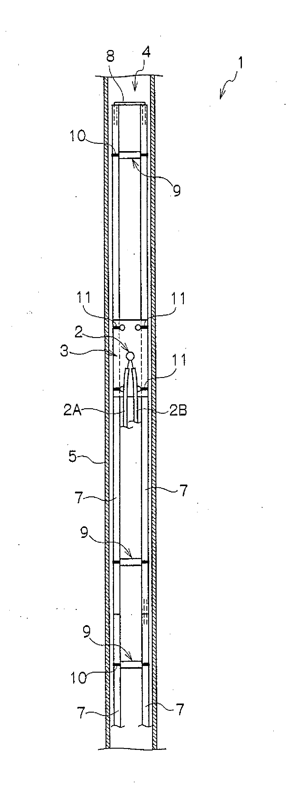
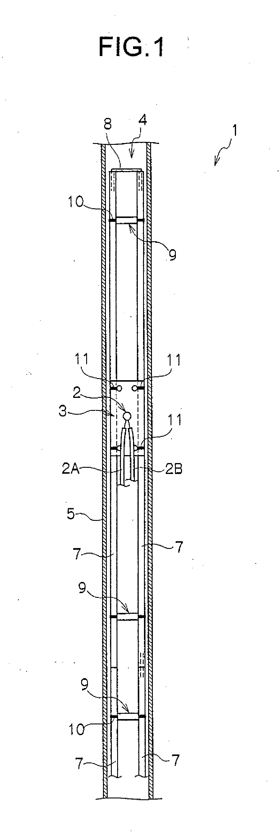
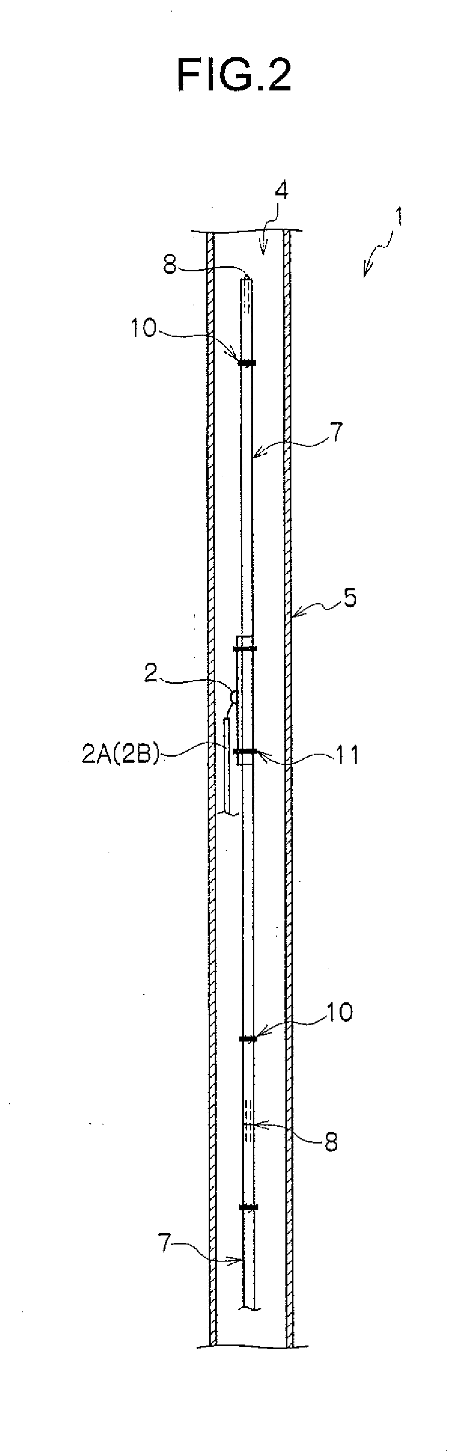
[0033]A temperature sensor 1 according to the present embodiment will be described based on FIGS. 1 to 3.

[0034]The temperature sensor 1 according to the present embodiment is configured to mainly include a temperature detecting element 2, a heat receiving body 3, a heat receiving body supporting mechanism 4, and a protective tube 5 as illustrated in the FIGS.

[0035]The temperature detecting element 2 is an element adapted to detect an ambient temperature. A thermocouple is used as the temperature detecting element 2. Another element may be used. Two cords 2A and 2B extend from the thermocouple as the temperature detecting element 2.

[0036]The heat receiving body 3 is a plate member to which the temperature detecting element 2 is fixed and that is heated by receiving surrounding heat. A plate member such as a silicon substrate, quartz, silicon carbide, and carbon can be used as the heat receiving body 3. The heat receiving body 3 is heated by receiving surrounding h...

second embodiment

(B) Second Embodiment

[0058]Next, a second embodiment of the present invention will be described.

[0059]A temperature sensor 14 according to the present embodiment is characterized by including a heat receiving body supporting joint. The other components are similar to those of the first embodiment.

[0060]A heat receiving body supporting mechanism 15 according to the present embodiment includes connecting narrow tubes 16, a connecting wire 17, and heat receiving body supporting joints 18 as illustrated in FIGS. 5 to 7.

[0061]The connecting narrow tubes16 and the connecting wire 17 (the connecting wire 17 illustrated in FIG. 5 in a state of passing through an inside of a center of a hole of a joint portion 20 in which the connecting narrow tube 16 is to be fitted) are similar to the connecting narrow tubes 7 and the connecting wire 8 described above. The length of the connecting narrow tube 16 according to the present embodiment is set in accordance with a position in which one wishes to...

third embodiment

(C) Third Embodiment

[0068]Next, a third embodiment of the present invention will be described based on FIGS. 8 to 10.

[0069]A temperature sensor 24 according to the present embodiment is characterized by improving the connecting rod 22 in the second embodiment. The other components are similar to those of the second embodiment.

[0070]A connecting rod 25 according to the present embodiment is configured as a different member from the respective joint portions 20 and supporting recess portions 21.

[0071]Accordingly, a heat receiving body supporting joint 26 includes a first piece 27 consisting of one joint portion 20 and one supporting recess portion 21, a second piece 28 consisting of the other joint portion 20 and the other supporting recess portion 21, and the connecting rod 25 having D-shaped end portions that are fitted in D-shaped hole portions provided in the first piece 27 and the second piece 28, respectively.

[0072]As for the connecting rod 25, ones having plural lengths are set...


PUM

PropertyMeasurementUnit
angleaaaaaaaaaa
temperatureaaaaaaaaaa
angleaaaaaaaaaa

Abstract

A rising characteristic of a temperature is improved, and high-accuracy temperature control is enabled. A temperature sensor according to the present invention includes a temperature detecting element, a heat receiving body to which the temperature detecting element is fixed and that is heated by receiving surrounding heat, a heat receiving body supporting mechanism supporting the heat receiving body at a predetermined position, and a protective tube adjusting the heat receiving body in a predetermined direction and at a predetermined position and holding the heat receiving body therein. In the temperature sensor, the heat receiving body is in a flat plate shape, the temperature detecting element is fixed to the heat receiving body, and the heat receiving body supporting mechanism includes a plurality of connecting narrow tubes connected to one another and a connecting wire passing through the respective connecting narrow tubes to connect and support all the connecting narrow tubes.

Description

CROSS-REFERENCE TO RELATED APPLICATION[0001]This application claims, under 35 USC 119, priority of Japanese Application No. 2012-027628 filed on Feb. 10, 2012.BACKGROUND OF THE INVENTION[0002]The present invention relates to a temperature sensor and a heat treating apparatus in which a method for fixing a temperature detecting element to be attached to an inside of a protective tube has been improved.[0003]In a conventional temperature sensor, a thermocouple as a temperature detecting element is fixed to a heat receiving body, is attached to an inside of a protective tube, and is fixed at a predetermined position as in Patent Document 1 (Japanese Patent Laid-Open No. 2002-296122) and Patent Document 2 (Japanese Patent Laid-Open No. 2001-208616), for example. The heat receiving body itself is not attached to a set position in the protective tube accurately but is attached to an inside of the protective tube together with the thermocouple.[0004]However, in the aforementioned conventio...

Claims


Application Information

Patent Timeline
Patent Type & Authority Applications(United States)
IPC IPC(8): G01K1/14
CPCG01K1/14
Inventor SAITO, TAKANORIYOSHII, KOJIKURIHARA, TSUTOMU
Owner FENWAL CONTROLS OF JAPAN
Why Eureka
Try Eureka