Temperature control device for optical glass window of temperature test box and using method

A technology of temperature test and optical glass, which is applied in the direction of testing optical performance and temperature control by electric means, which can solve the problems of easy change of optical glass coating optical parameters, inability to realize temperature control, and inability to eliminate the change of optical glass surface shape, etc. Achieve the effects of avoiding frost, high-precision temperature control, and reducing the impact of convection

Pending Publication Date: 2021-04-16
XI'AN INST OF OPTICS & FINE MECHANICS - CHINESE ACAD OF SCI
View PDF0 Cites 0 Cited by
  • Summary
  • Abstract
  • Description
  • Claims
  • Application Information

AI Technical Summary

Problems solved by technology

[0008] The purpose of the present invention is to solve the problem that existing optical glass window temperature control device and using method of temperature test chamber adopt the method of blowing dry air or nitrogen to the outer surface of the optical glass, which cannot eliminate the temperature gradient on the surface of the optical glass, and adopt a heating film to control the temperature of the outer surface of the optical glass. The surface heating method is easy to change the optical parameters of the original coating of the optical glass, and the temperature control under the high temperature test cannot be realized, and these two methods cannot eliminate the technical problem of the surface shape change caused by the temperature difference between the inner and outer surfaces of the optical glass. Provided is a temperature control device for optical glass windows in a temperature test chamber and a method of use thereof. Through temperature control, the inner and outer surfaces of the optical glass are closer to room temperature, and the surface shape of the optical glass caused by the temperature is effectively controlled, which is conducive to improving the accuracy of optical testing.

Method used


Image

  • Temperature control device for optical glass window of temperature test box and using method

Examples


Embodiment Construction

[0040] The present invention will be further described below in conjunction with the accompanying drawings and embodiments.

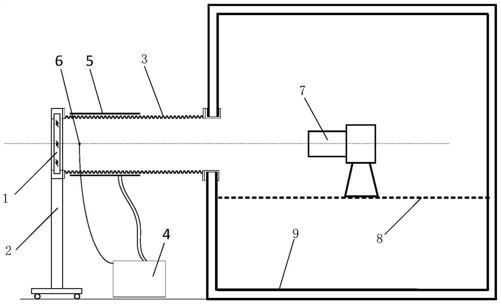
[0041] The invention provides a temperature control device for the optical glass window of a temperature test box, such as figure 1As shown, it includes optical glass 1, mounting bracket 2, metal bellows 3, temperature controller 4, temperature control circuit 5 and main temperature sensor 6; the optical glass 1 is embedded in the center of the optical glass flange, and the optical glass flange Installed on the mounting bracket 2 (rigid connection); the two ends of the metal bellows 3 have flanges, the flange at one end is connected to the optical glass flange, and the flange at the other end is connected to the temperature test box 9. The window flange of the metal bellows 3 is provided with a through hole on the side wall near the end of the optical glass 1, and a sealing plug is provided in the through hole to seal the opening position; the temperatu...


PUM


Abstract

The invention relates to a temperature control device for an optical glass window of a temperature test box and a using method. The invention aims to solve the technical problems that the temperature gradient of the surface of the optical glass cannot be eliminated, the original coating optical parameters of the optical glass are easy to change, the temperature control under a high-temperature test cannot be achieved, and the surface shape change of the inner surface and the outer surface of the optical glass caused by temperature difference cannot be eliminated in the prior art. The invention provides a temperature control device for an optical glass window of a temperature test box and a using method. The convex design of the optical glass is achieved by utilizing the metal corrugated pipe, and a buffer area is formed in the metal corrugated pipe, so that the flow of circulating gas in the temperature test box near the inner surface of the optical glass is reduced, more tooling areas are in contact with air at room temperature in a laboratory, and the temperature of the optical glass is closer to the room temperature. The inner and outer surfaces of the optical glass are closer to the room temperature through temperature control, the surface shape problem of the optical glass caused by temperature is effectively controlled, and the optical test precision is improved.

Description

technical field [0001] The invention relates to a temperature control device and a use method, in particular to a temperature control device and a use method for an optical glass window of a temperature test chamber, which are suitable for optical index testing of optical machine products in ground high and low temperature tests. Background technique [0002] According to the requirements of the reliability test, the optomechanical products need to undergo high and low temperature tests on the ground to check whether the optical indicators of the optomechanical products meet the design requirements in the high and low temperature environment. In order to meet the needs of optical testing of optical and mechanical products in high and low temperature test chambers, the optical glass for optical testing is generally installed on the window on the wall of the temperature test chamber with a flange (inside the flange), that is, the optical glass is installed on the On the wall o...

Claims


Application Information

Patent Timeline
Patent Type & Authority Applications(China)
IPC IPC(8): G01M11/02G05D23/19
Inventor 高斌赛建刚张海民王亚军赵燕高博贾琦陈建涛
Owner XI'AN INST OF OPTICS & FINE MECHANICS - CHINESE ACAD OF SCI
Why Eureka
Try Eureka