heating device

A heating device and heating body technology, which is applied to electric heating devices, engine ignition, engine components, etc., can solve the problems of increased manufacturing cost, decrease in the temperature and heating rate of glow plugs, and decrease in heating temperature, so as to achieve manufacturing cost, Excellent mountability and simple structure

Inactive Publication Date: 2016-03-23
DENSO CORP
View PDF7 Cites 0 Cited by
  • Summary
  • Abstract
  • Description
  • Claims
  • Application Information

AI Technical Summary

Problems solved by technology

[0017] Therefore, among a plurality of glow plugs, even if excessive temperature rise of the glow plug with a low resistance value can be avoided, the attained temperature and temperature rise rate of the glow plug with a high resistance value may decrease.
[0018] In addition, in the glow plug energization control device such as Patent Document 3, environmental information such as engine water temperature is used, so the control method is complicated, and a CPU with high computing processing capacity and an interrupt timer are required. Due to the increase in size, it may be difficult to install in the engine room where various electronic control devices are highly integrated
[0019] In addition, in the conventional glow plug energization control device, in order to control the heat generation temperature of the glow plug more accurately or to detect the abnormality of the glow plug, the glow plug current flowing in the glow plug and the current applied to the glow plug are compared. The voltage of the glow plug is A / D converted and sent to the ECU side, and the arithmetic processing is performed on the ECU side and used for stopping or temperature correction of the glow plug power supply control device, and the amount of data transmitted between the glow plug power supply control device and the ECU becomes smaller. Therefore, a high-performance CPU is required, or a high-speed data communication unit such as CAN is required, and the increase in manufacturing cost cannot be avoided.
[0020] In addition, when a certain target power is applied in a manner like Patent Document 3, there is a big problem that the actual heating temperature drops below the target temperature due to the influence of eddy currents.

Method used


Image

  • heating device
  • heating device
  • heating device

Examples


Embodiment Construction

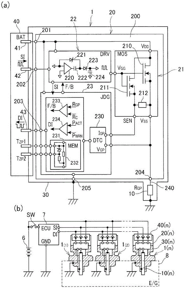
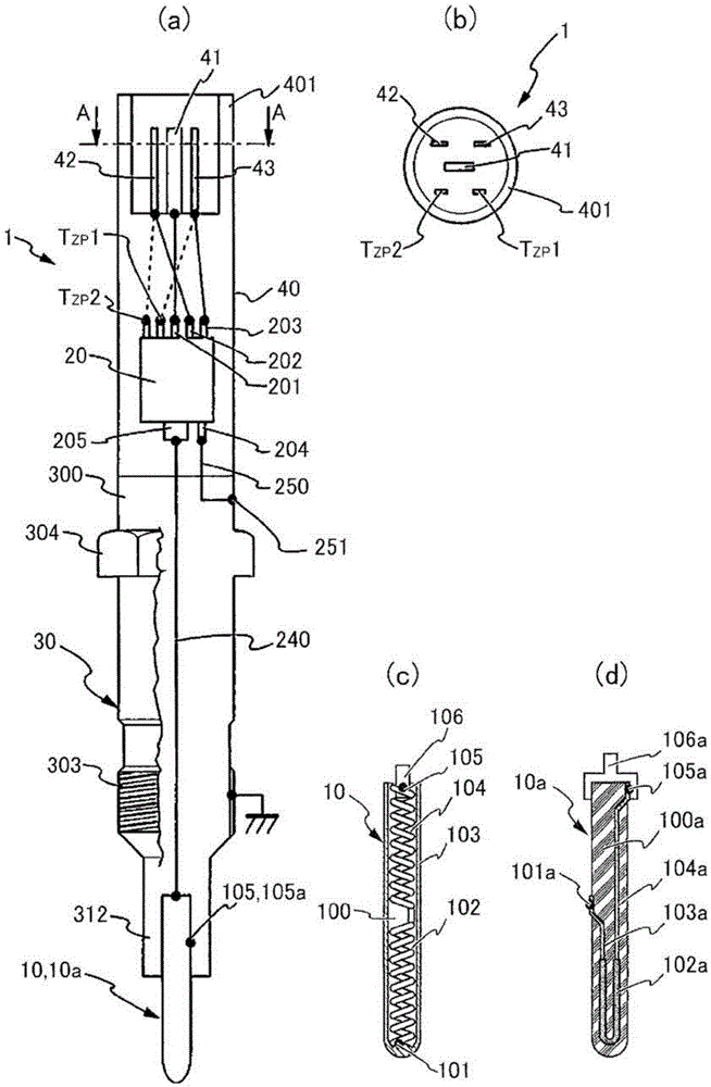
[0047] As the heat generating device in the embodiment of the present invention, a heat generating body 10 provided in each cylinder of an internal combustion engine (not shown) is used as a heat generating body, and an energization control module 20 for controlling energization from the power supply 6 to the heat generating body 10 is integrated. The controller-integrated glow plug 1 accommodated in the housing 30 .

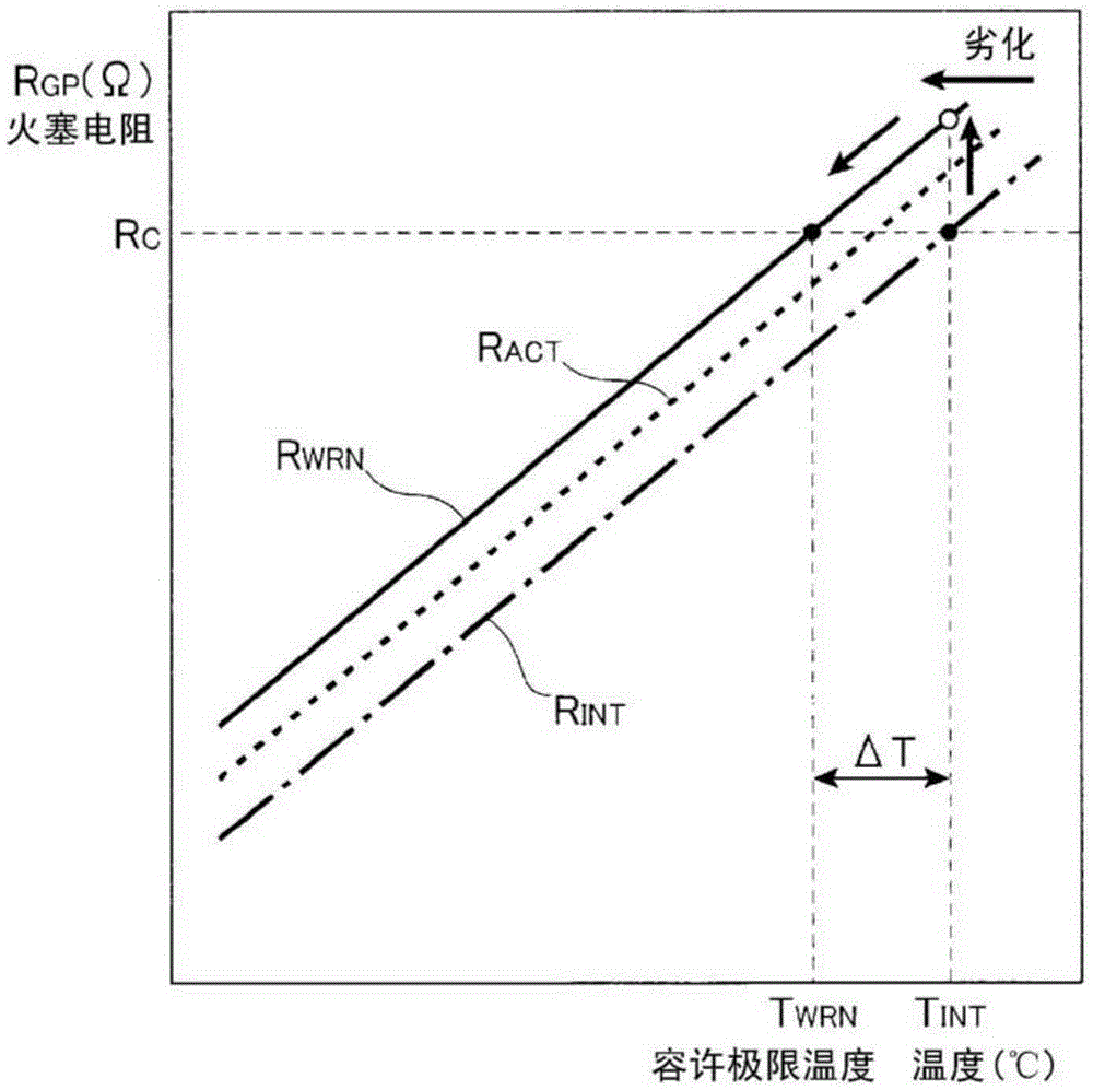
[0048] Such as figure 1 As shown, in the controller-integrated glow plug 1 of the present embodiment, it is equipped with: a heating element 10 that generates heat when energized, and its resistance value changes in a positive correlation with its own temperature change; an energization control module 20 , so that the resistor value R GP with the target resistor value R TRG In a consistent manner, the power supply from the power supply 6 to the heating element 10 is controlled; the reference resistance value storage unit 231 houses the heating element 10 integ...


PUM


Abstract

A heating device (1) has a heating element (10) capable of generating heat energy when receiving an electric power, and a power supply control module (20) for performing a power supply so that a plug resistance value R GP of the heating element becomes equal to a target resistance value R TRG . The heating element and the electric power supply control module are accommodated together in a housing casing (30) of a cylinder-like shape. The power supply control device (20) has a reference resistance value storage means (231) for storing a resistance value of the heating device, as a reference resistance value R C , at a predetermined target temperature T TRG , a resistance value change reflecting means (233) and a deterioration judgment means (234). The resistance value change reflecting means (233) allows the power supply to the heating element (10) when the plug resistance value R GP of the heating element (10) is lower than the reference resistance value R C during the power supply to the heating element (10), and halts the power supply to the heating element (10) when the plug resistance value R GP of the heating element (10) exceeds the reference resistance value R C during the power supply to the heating element (10) in order to reflect, to the power supply control, the resistance value change due to the temperature change of the heating element (10). The deterioration judgment means (234) judges whether or not the heating element (10) is deteriorated by using a deterioration power value P WRN in a deterioration state, as a power threshold value P REF , calculated by multiplying an initial reference power value P INT with a predetermined rate.

Description

technical field [0001] The present invention relates to a heating device with a heating body and an energization control module, which realizes stable energization control and rapid abnormal deterioration detection through a simple structure, and is especially suitable for a glow plug installed in each cylinder of a diesel combustion mechanism. ) is a glow plug integrated with a control unit as a heating element, and the heating element and the energization control module are integrally accommodated in a substantially cylindrical casing. And having positive correlation changes, the above-mentioned energization control module controls the energization from the power supply to the heating element. Background technique [0002] Conventionally, as an abnormality detection device for detecting a disconnection abnormality or an overcurrent abnormality of a glow plug that assists ignition of a diesel combustion mechanism, a device is known in which a device is provided between the ...

Claims


Application Information

Patent Timeline
Patent Type & Authority Patents(China)
IPC IPC(8): H05B3/00
CPCH05B1/0236F02P19/021F02P19/022F02P19/023F02P19/025F02P19/027F23Q7/001H05B2203/02H05B2203/027
Inventor 入江将嗣深泽剛山口宏尚林真人
Owner DENSO CORP
Why Eureka
Try Eureka