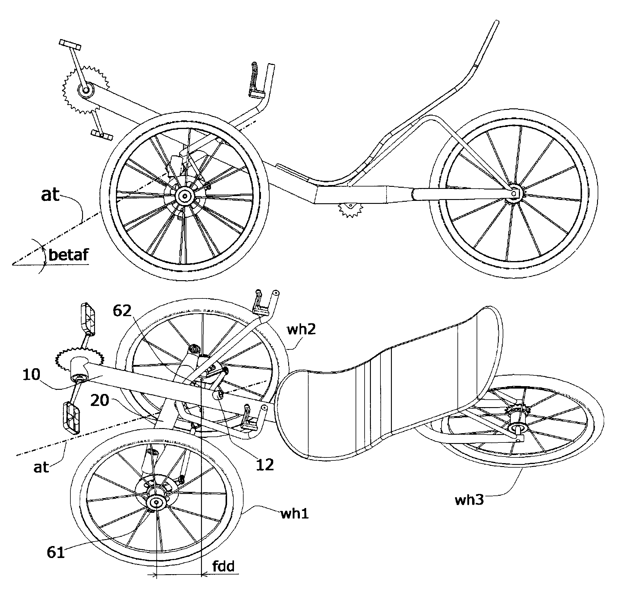
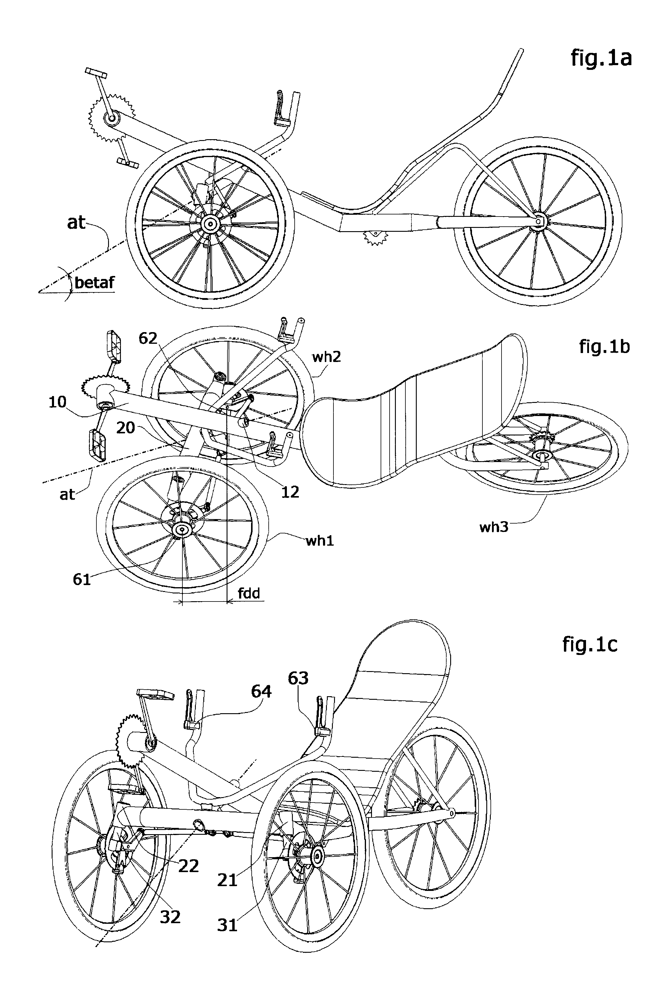
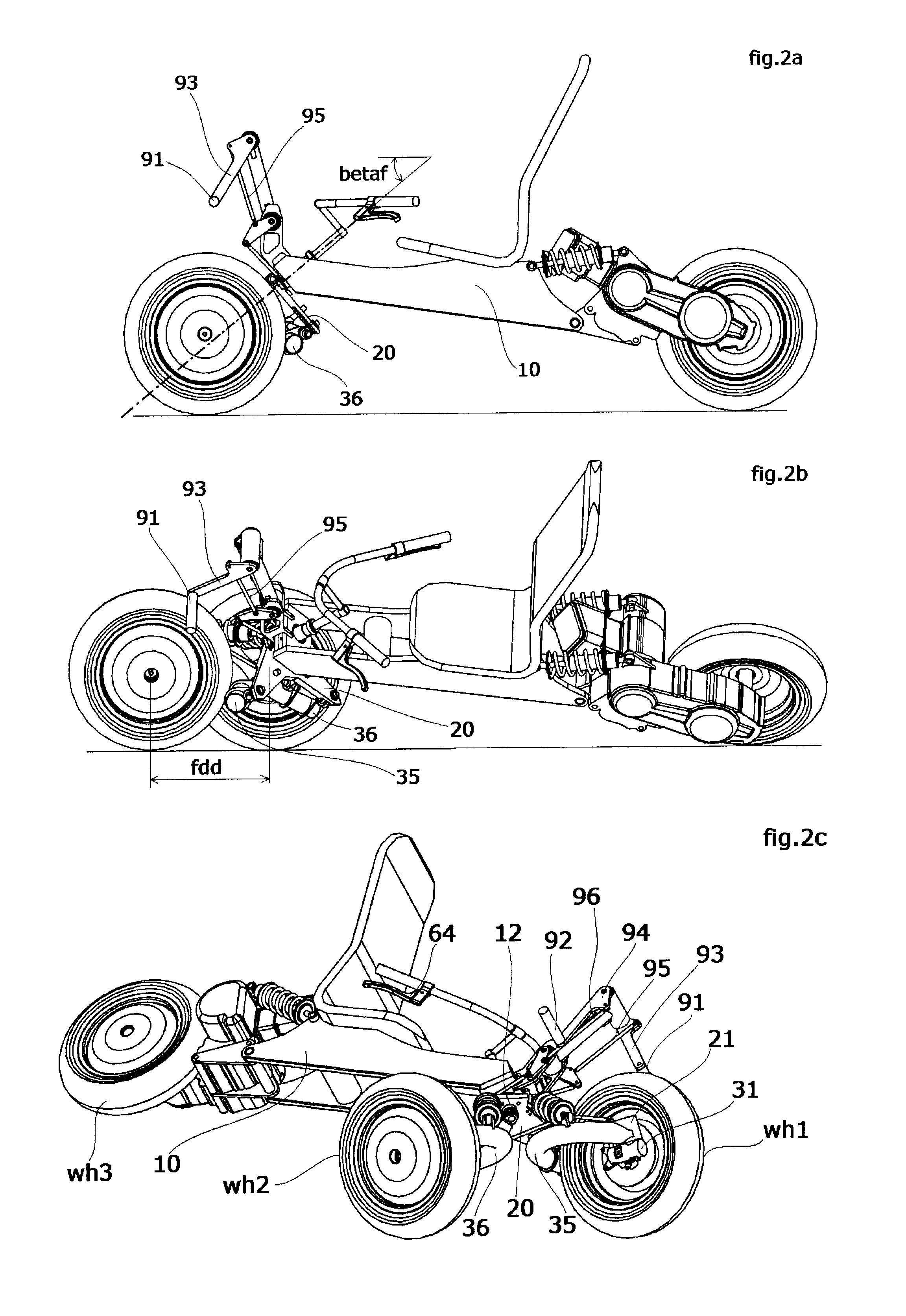
Devices To Let A Tilting Vehicle Lean When Driving And To Keep It Standing When Stopped
a technology of tilting vehicle and stand device, which is applied in the field of narrow vehicles, can solve the problems of increasing the risk of vehicle rollover due to centrifugal force in a bend, adding stand device, and increasing the weight, complexity and cost of free tilting vehicle, so as to improve the aerodynamic resistance and stability to lateral wind, increase the driving ability, and improve the effect of stability
- Summary
- Abstract
- Description
- Claims
- Application Information
AI Technical Summary
Benefits of technology
Problems solved by technology
Method used
Image
Examples
first embodiment
Description of a First Embodiment
[0171]In FIG. 4a, 4b, 4c, the inventive concept is applied to a free tilting road vehicle with three wheels (wh1, wh2, wh3), all the wheels being tilting with the vehicle. The tilting device has a transverse beam (20) and arms (40, 50) steering axle, all pivotally or rotatably connected to a trailing arm suspension (70). More specifically the transverse beam (20) is pivotally connected to the trailing arm (70) by means of pivot (72) with a suitable tilt axis incidence (betaf) from high-back to low-front and with the tilt axis (at) lying on the vehicle's symmetry plane, whilst the arms (40, 50) are rotatably connected to the trailing arm (70) by means of spherical pairs (41, 51). Furthermore the trailing arm is pivotally linked to the vehicle's chassis (10) by means of a couple of coaxial pivots (71, 72) perpendicular to the vehicle's symmetry plane.
[0172]FIG. 4a is the left-side views of said vehicle perpendicular to the ground and without the left w...
second embodiment
Description of a Second Embodiment
[0188]FIG. 6a is a left-side view of a free tilting three wheeler perpendicular to the ground, with a transverse beam and arms linkage which is rotatably connected, and at the same time suspended, to the chassis (10) of the tilting vehicle by means of a longitudinal rotoreflected double wishbone suspension (70, 20, 80), hereinafter called “longitudinal tilting suspension”.
[0189]In FIG. 6a the tilt axis is identifiable as the line between the spherical pairs (12) and (74), inclined from high-back to low-front.
[0190]FIG. 6b is a left side-view of the same vehicle, tilted by an angle ro=30 deg, approximately, where the tilting of the lower arm of said suspension (70) can be seen.
[0191]FIG. 6c is a three quarters front and left-side view of the same vehicle perpendicular to the ground where the transverse beam and arms steering axle is identifiable.
[0192]Said transverse beam and arm linkage is equivalent to the homonymous linkage described in the first ...
PUM
 Abstract
Description
Claims
Application Information
 - R&D
- Intellectual Property
- Life Sciences
- Materials
- Tech Scout
- Unparalleled Data Quality
- Higher Quality Content
- 60% Fewer Hallucinations
Browse by: Latest US Patents, China's latest patents, Technical Efficacy Thesaurus, Application Domain, Technology Topic, Popular Technical Reports.
© 2025 PatSnap. All rights reserved.Legal|Privacy policy|Modern Slavery Act Transparency Statement|Sitemap|About US| Contact US: help@patsnap.com


