3D scene model from video

a three-dimensional scene and video technology, applied in the field of digital imaging, can solve the problems of wasting computational effort, reducing the view redundancy of a frame sequence, and only practical approaches for relatively small datasets, so as to reduce the number of video frames, improve the efficiency of the three-dimensional reconstruction process, and improve the effect of image quality

Inactive Publication Date: 2013-08-22
INTELLECTUAL VENTURES FUND 83 LLC
View PDF5 Cites 72 Cited by
  • Summary
  • Abstract
  • Description
  • Claims
  • Application Information

AI Technical Summary

Benefits of technology

[0021]This invention has the advantage that the efficiency of the three-dimensional reconstruction process is improved by reducing the number of video frames that are analyzed.
[0022]It has the additional advantage that the video frames are selected taking account for any no

Problems solved by technology

However, due to scalability issues with the MVS algorithms, it has been found that these approaches are only practical for relatively small datasets (see: Seitz et al., “A comparison and evaluation of multi-view stereo reconstruction algorithms,” Proc.
Although these methods can calculate the depth maps in parallel, the depth maps tend to be noisy and highly redundant, which results in a waste of computational effort.
However, this approach is not very effective in reducing the view redundancy for a frame sequence in a video.
However, both methods are only suitable for highly structured datasets (e. g., street-view datasets obtained by a video camera mounted on a moving van).
Unfortunately, for consumer videos taken using hand-held video cameras the video frame sequences are more disordered and less structured than the videos that these methods were designed to process.
More specifically, the camera trajectories for the consumer videos are not smooth, and typically include a lot of overlap (i.e., frames captured at redundant locations).
However, most IBR methods either synthesize a new view from only one original frame using little geometry information, or require accurate geometr

Method used


Image

  • 3D scene model from video
  • 3D scene model from video
  • 3D scene model from video

Examples


Embodiment Construction

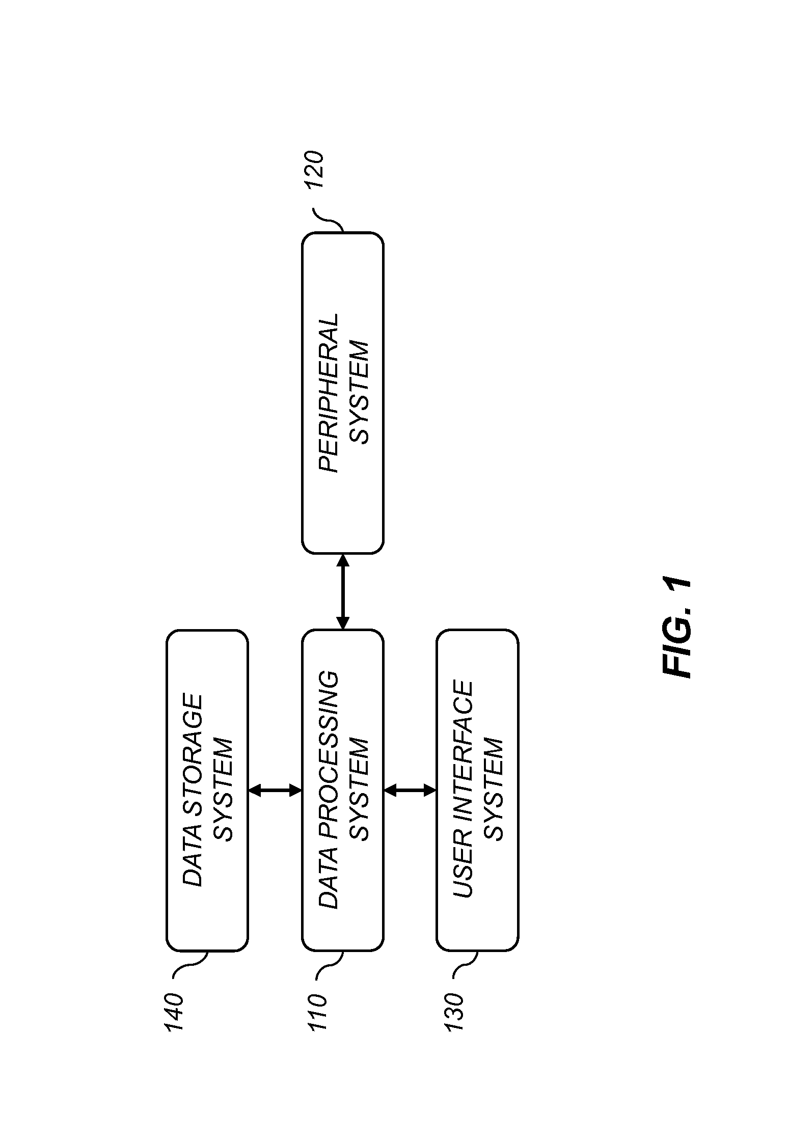
[0037]In the following description, some embodiments of the present invention will be described in terms that would ordinarily be implemented as software programs. Those skilled in the art will readily recognize that the equivalent of such software may also be constructed in hardware. Because image manipulation algorithms and systems are well known, the present description will be directed in particular to algorithms and systems forming part of, or cooperating more directly with, the method in accordance with the present invention. Other aspects of such algorithms and systems, together with hardware and software for producing and otherwise processing the image signals involved therewith, not specifically shown or described herein may be selected from such systems, algorithms, components, and elements known in the art. Given the system as described according to the invention in the following, software not specifically shown, suggested, or described herein that is useful for implement...


PUM


Abstract

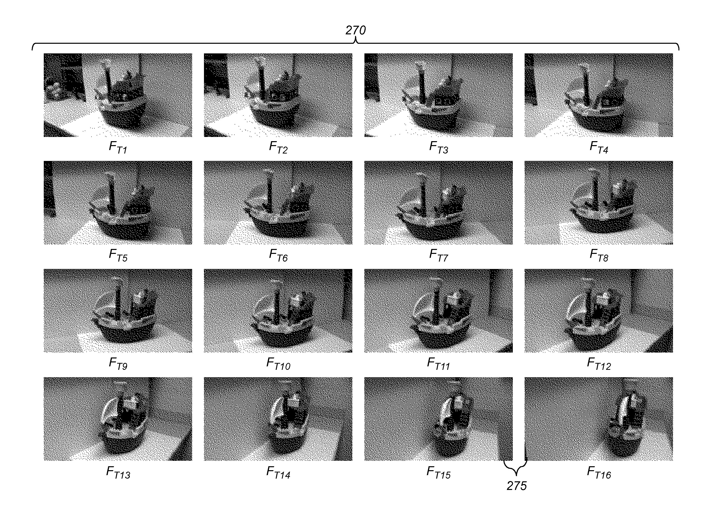
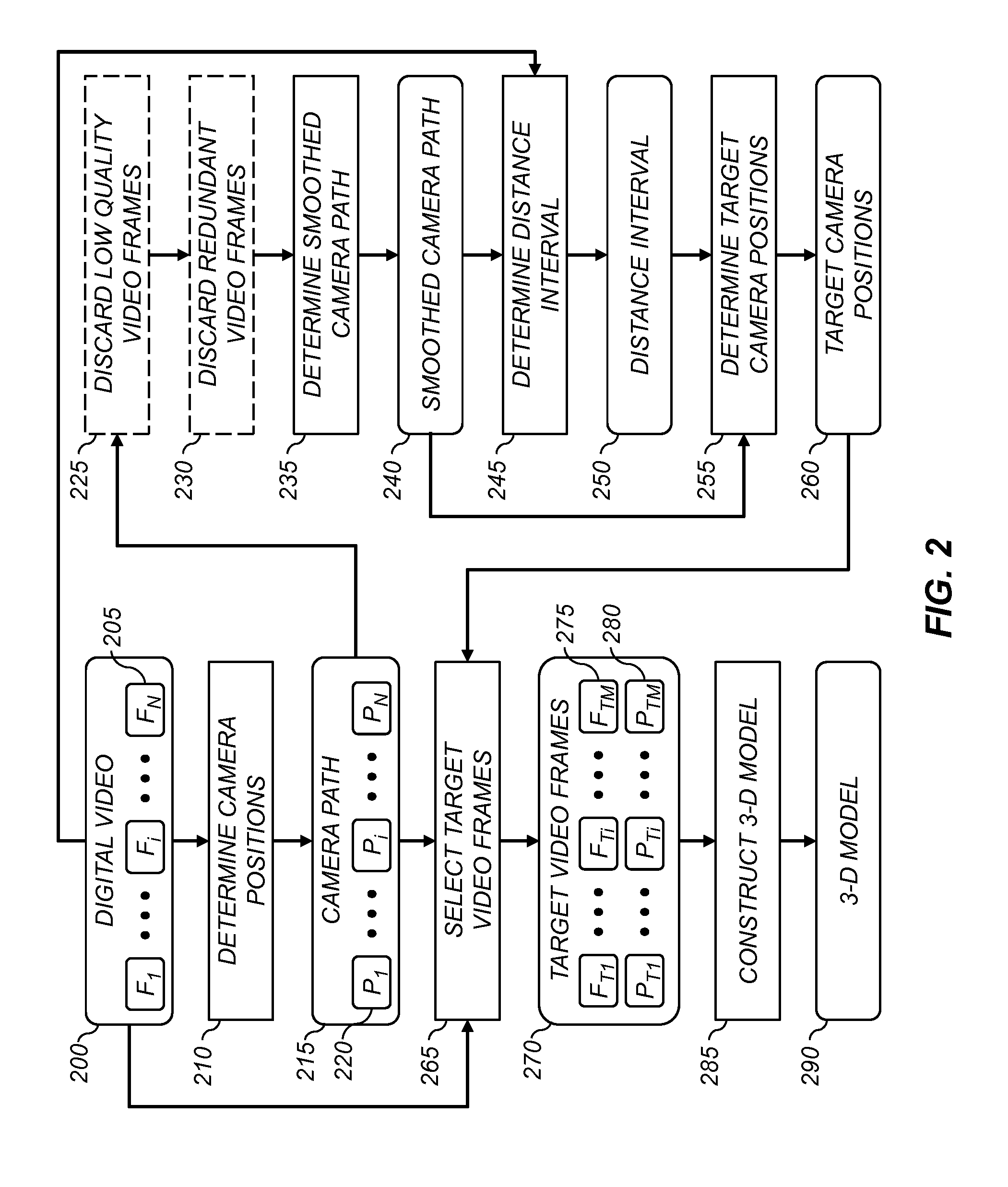
A method for determining a three-dimensional model of a scene from a digital video captured using a digital video camera, the digital video including a temporal sequence of video frames. The method includes determining a camera position of the digital video camera for each video frame, and fitting a smoothed camera path to the camera positions. A sequence of target camera positions spaced out along the smoothed camera path is determined such that a corresponding set of target video frames has at least a target level of overlapping scene content. The target video frames are analyzed using a three-dimensional reconstruction process to determine a three-dimensional model of the scene.

Description

CROSS-REFERENCE TO RELATED APPLICATIONS[0001]Reference is made to commonly assigned, co-pending U.S. patent application Ser. No. 13 / 298,332 (Docket K000574), entitled “Modifying the viewpoint of a digital image”, by Wang et al.; to commonly assigned, co-pending U.S. patent application Ser. No. ______ (Docket K000900), entitled “3D scene model from collection of images” by Wang; to commonly assigned, co-pending U.S. patent application Ser. No. ______ (Docket K000492), entitled “Key video frame selection method” by Wang et al., each of which is incorporated herein by reference.FIELD OF THE INVENTION[0002]This invention pertains to the field of digital imaging and more particularly to a method for determining a three-dimensional scene model from a digital video.BACKGROUND OF THE INVENTION[0003]Much research has been devoted to two-dimensional (2-D) to three-dimensional (3-D) conversion techniques for the purposes of generating 3-D models of scenes, and significant progress has been mad...

Claims


Application Information

Patent Timeline
IPC IPC(8): H04N13/02
CPCG06T7/0071G06T2207/30244G06T2207/30241G06T2207/10016G06T7/579
Inventor WANG, SENZHONG, LIN
Owner INTELLECTUAL VENTURES FUND 83 LLC
Why Eureka
Try Eureka