Decoupler with tuned damping and methods associated therewith

Active Publication Date: 2013-08-22
LITENS AUTOMOTIVE INC
View PDF17 Cites 74 Cited by
  • Summary
  • Abstract
  • Description
  • Claims
  • Application Information

AI Technical Summary

Benefits of technology

[0006]The damping torque may be selected to provide less than a selected maximum amount of torsional vibration to the hub of the decoupler particularly in a selected frequency range. In particular providing less than the selected maximum amount of torsional vibration to the hub of the decoupler in the selected frequency range is useful when the decoupler is connected to a shaft of an alternator. It has been found that this inhibits the voltage regulator of the alternator from controlling the alternator at a switching frequency that is in the range of 15 Hz, which may be near the natural frequency of the decoupler. Inhibiting the alternator from having such a switching frequency reduces any torsional vibration induced in the hub from the alternator, in that frequency range. This reduces the overall torsional vibration incurred by the hub, which improves the fatigue life of the isolation spring.
[0007]Through significant testing it has been found that the voltage regulator of the alternator may be upset by current fluctuations that result from first order vibrations that are incurred by the alternator rotor. When this occurs,

Problems solved by technology

Through significant testing it has been found that the voltage regulator of the alternator may be upset by current fluctuations that result from first order vibrations that are incurred

Method used


Image

  • Decoupler with tuned damping and methods associated therewith
  • Decoupler with tuned damping and methods associated therewith
  • Decoupler with tuned damping and methods associated therewith

Examples


Embodiment Construction

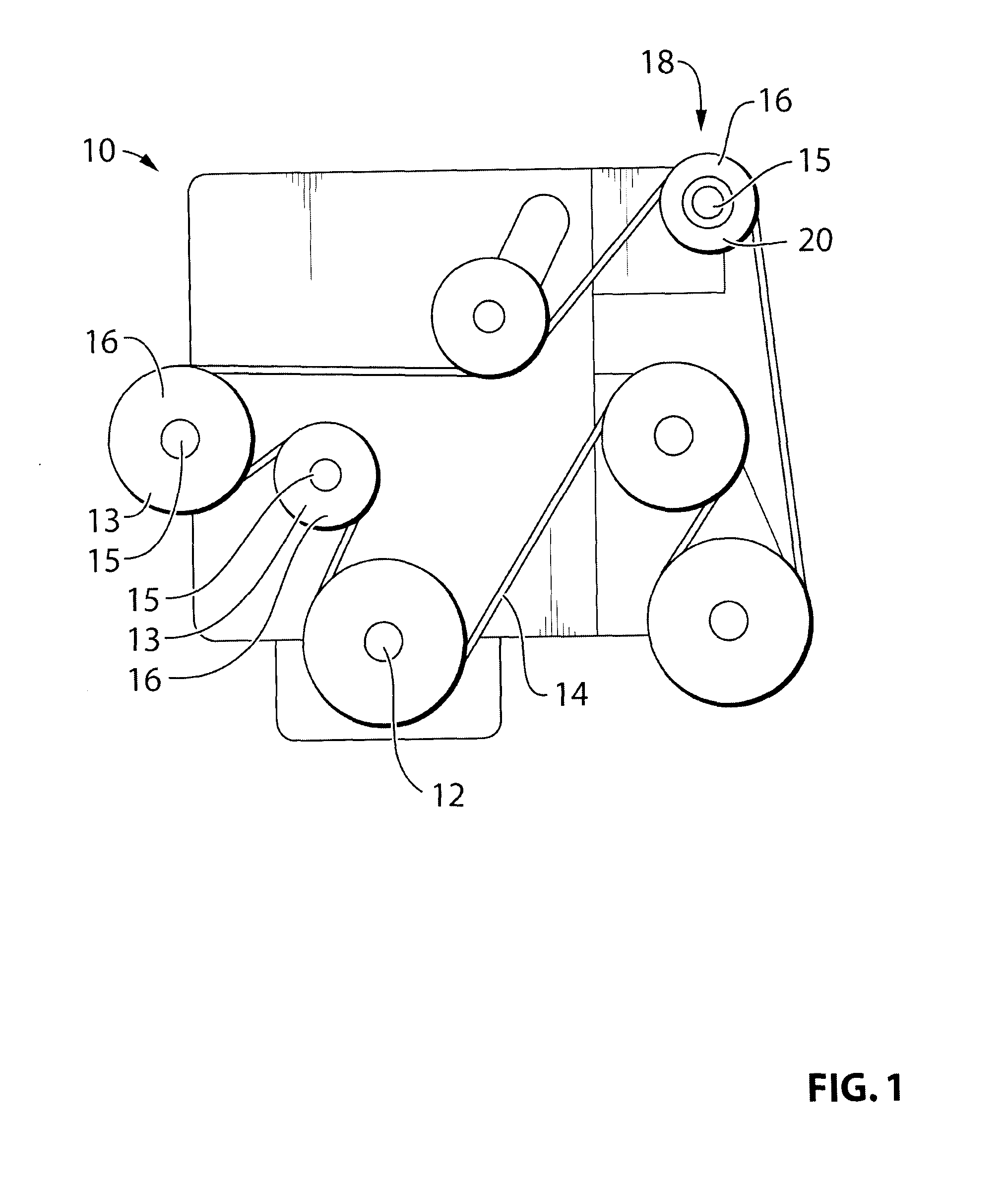
[0027]Reference is made to FIG. 1, which shows an engine 10 for a vehicle. The engine 10 includes a crankshaft 12 which drives an endless drive element, which may be, for example, a belt 14. Via the belt 14, the engine 10 drives a plurality of accessories 16 (shown in dashed outlines), such as an alternator 18. Each accessory 16 includes an input drive shaft 15 with a pulley 13 thereon, which is driven by the belt 14. A decoupler 20 is provided instead of a pulley, between the belt 14 and the input shaft 15 of any one or more of the belt driven accessories 16, an in particular the alternator 18.

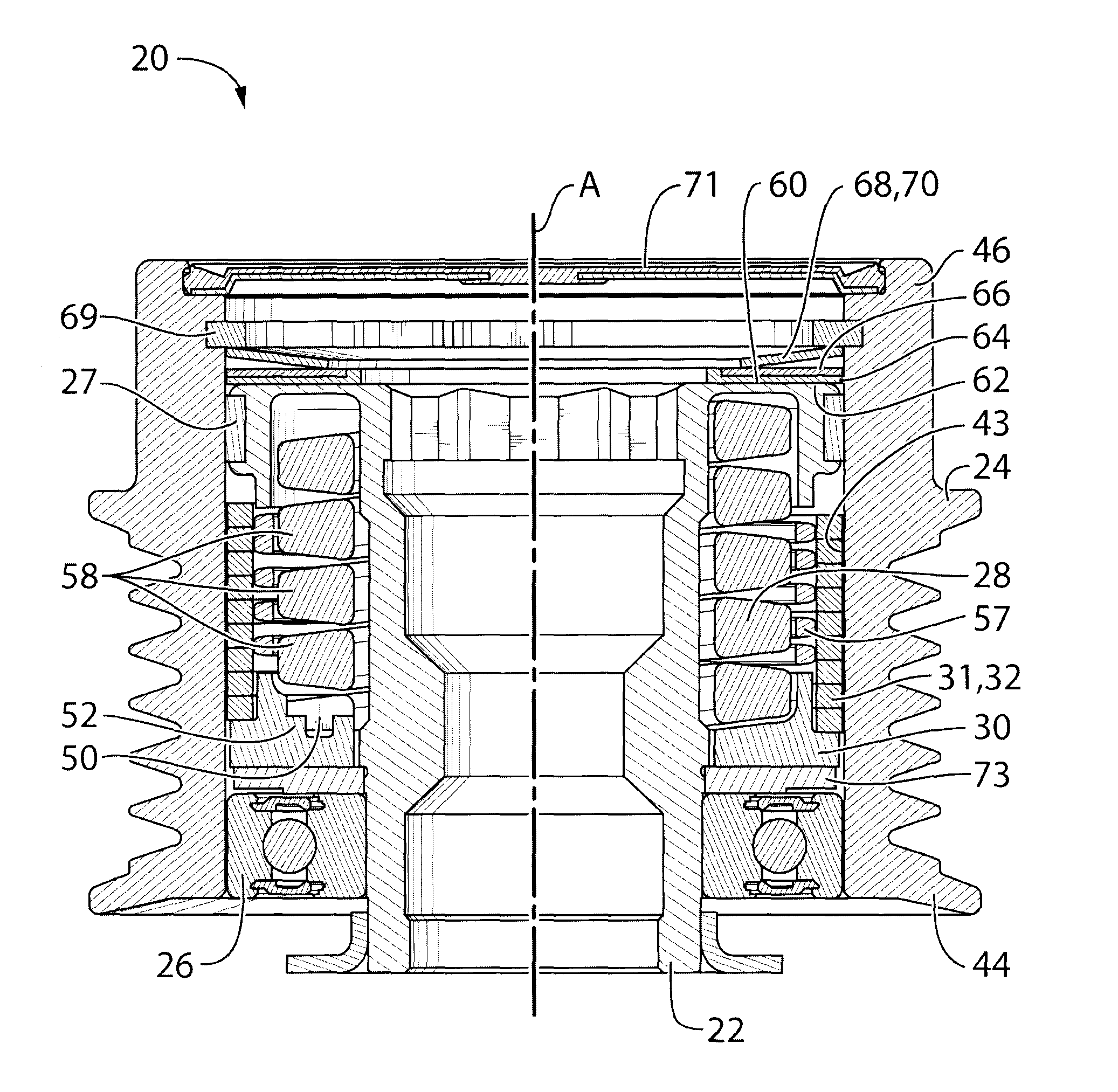
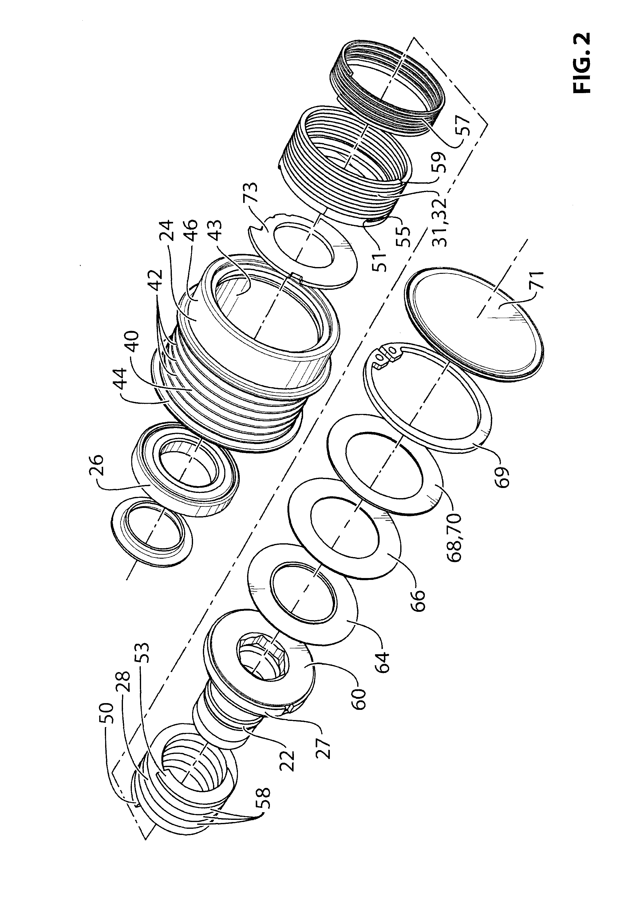
[0028]Reference is made to FIG. 2, which shows a sectional view of the decoupler 20. The decoupler 20 includes a hub 22, a pulley 24, a first bearing member 26, a second bearing member 27, an isolation spring 28, a carrier 30, and a one-way clutch 31, which in this exemplary embodiment is a one-way wrap spring clutch comprising a wrap spring 32.

[0029]The hub 22 may be adapted to mount to the ...


PUM

PropertyMeasurementUnit
Angleaaaaaaaaaa
Frequencyaaaaaaaaaa
Frequencyaaaaaaaaaa

Abstract

In an aspect, the invention relates to a decoupler that is positionable between a shaft (eg. for an alternator) and an endless power transmitting element (eg. a belt) on an engine. The decoupler includes a hub that mounts to the shaft, and a pulley that engages the endless power transmitting element, an isolation spring between the hub and the shaft. The decoupler provides at least a selected damping torque between the hub and the pulley.

Description

[0001]This application claims the benefit of U.S. Provisional Application No. 61 / 414,682, filed Nov. 17, 2010, and U.S. Provisional Application No. 61 / 413,475, filed Nov. 14, 2010, the contents of both of which are incorporated herein by reference in their entireties.FIELD OF THE INVENTION[0002]The present invention relates to decoupling mechanisms for allowing belt driven accessories to operate temporarily at a speed other than the speed of the belt, and more particularly to decoupling mechanisms for alternators.BACKGROUND OF THE INVENTION[0003]It is known to provide a decoupling mechanism on an accessory, such as an alternator, that is driven by a belt from the crankshaft of an engine in a vehicle. Such a decoupling mechanism, which may be referred to as a decoupler assembly or a decoupler, permits the associated accessory to operate temporarily at a speed that is different than the speed of the belt. As is known, the crankshaft undergoes cycles of accelerations and decelerations ...

Claims


Application Information

Patent Timeline
IPC IPC(8): F16D3/12F16D3/14
CPCF02B67/06F16D3/12F16D7/025Y10T29/49764F16H55/36F16H2055/366F16D3/14F16D41/206B60K25/00F16D7/02F16F15/12F16H7/20
Inventor ANTCHAK, JOHN R.XU, JUNMARION, PATRICKWILSON, LUCASBOUDREAU, JUSTINSPICER, GARY J.
Owner LITENS AUTOMOTIVE INC
Why Eureka
Try Eureka