Control apparatus for vehicular drive system
- Summary
- Abstract
- Description
- Claims
- Application Information
AI Technical Summary
Benefits of technology
Problems solved by technology
Method used
Image
Examples
embodiment
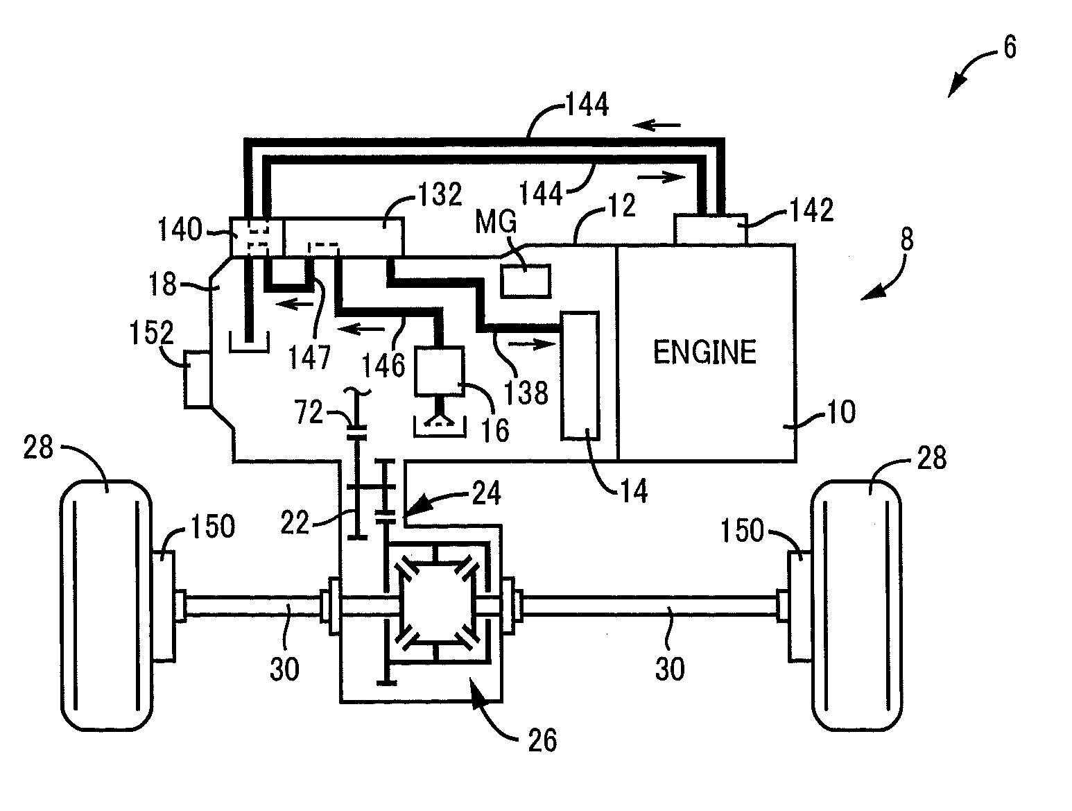
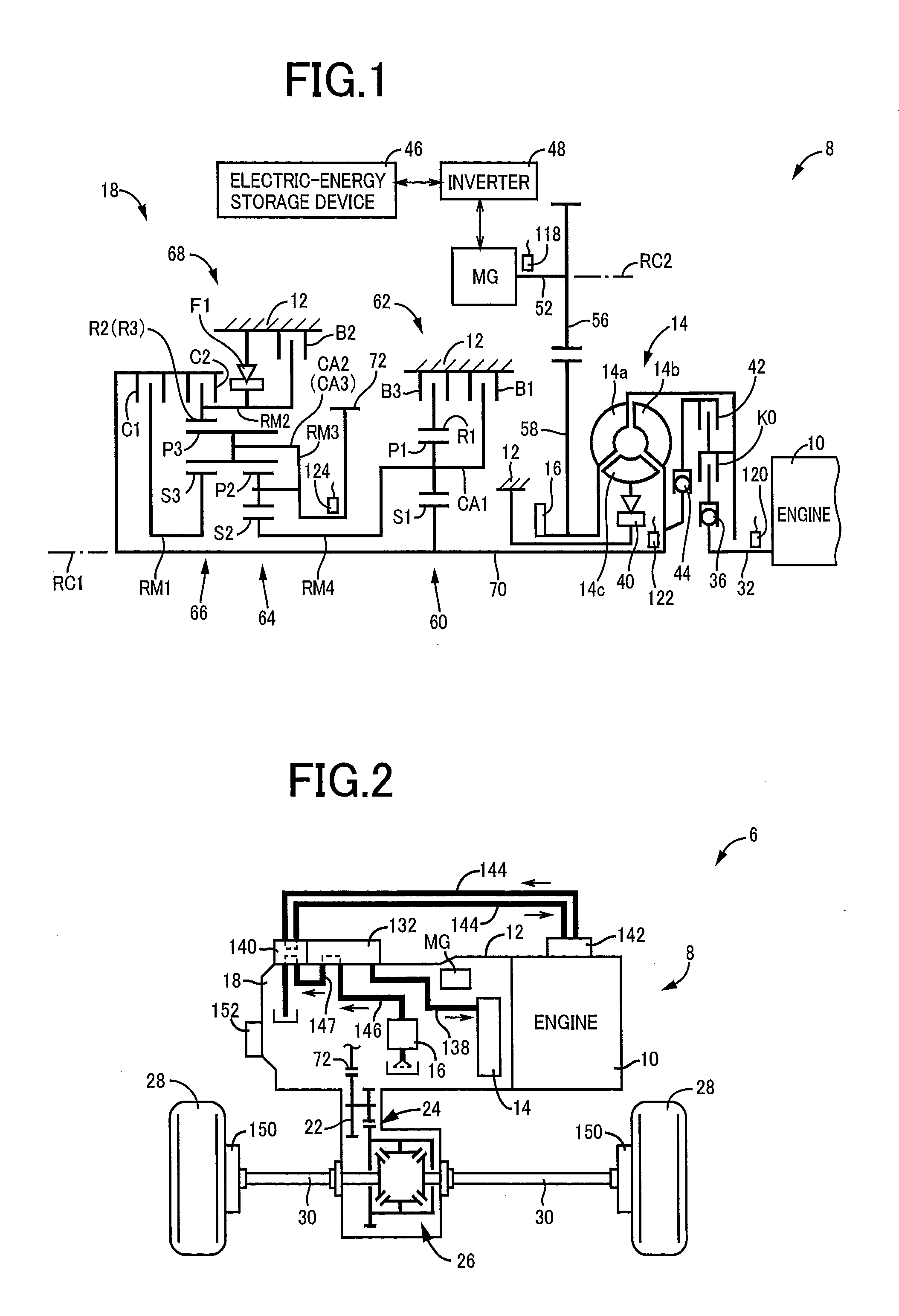
[0030]FIG. 1 is the schematic view of a vehicular drive system 8 (hereinafter referred to as “drive system 8”) to which the present invention is suitably applicable, and FIG. 2 is the view showing a power transmitting path from the drive system 8 to drive wheels 28. It is noted that an automatic transmission 18, a torque converter 14, etc. are substantially symmetric in construction with respect to their axes (first axis RC1), so that their lower halves are not shown in FIG. 1. The first axis RC1 shown in FIG. 1 represents the axes of an engine 10 and the torque converter 14, while a second axis RC2 represents the axis of an electric motor MG.
[0031]As shown in FIG. 1, the drive system 8 has the engine 10 of an water-cooled type such as a gasoline engine, a diesel engine or any other internal combustion engine, and a transaxle casing (T / A casing) 12 (hereinafter referred to as “casing 12”) which is a stationary member fixed to a vehicle body by bolts or any other fixing means. Within...
PUM
 Abstract
Description
Claims
Application Information
 - R&D
- Intellectual Property
- Life Sciences
- Materials
- Tech Scout
- Unparalleled Data Quality
- Higher Quality Content
- 60% Fewer Hallucinations
Browse by: Latest US Patents, China's latest patents, Technical Efficacy Thesaurus, Application Domain, Technology Topic, Popular Technical Reports.
© 2025 PatSnap. All rights reserved.Legal|Privacy policy|Modern Slavery Act Transparency Statement|Sitemap|About US| Contact US: help@patsnap.com


